
Wien Bridge RC Sinewave Oscillator


The Wien Bridge oscillator is a type of electronic oscillator that generates sine waves. It utilizes a bridge circuit to achieve the necessary phase shift for oscillation. In the discussed configurations, the oscillators are designed to provide a 360-degree phase shift, which is essential for sustaining oscillations. The first configuration employs three bipolar transistors, where the gain is critically managed to avoid distortion or failure to oscillate. The automatic gain control (AGC) mechanism, implemented using a light bulb, is pivotal for maintaining stable oscillation levels.
In the second example, the integration of a JFET simplifies the circuit by providing high input impedance and self-biasing capabilities. This configuration allows for fewer components while maintaining similar gain levels. The adjustment of the drain resistor is crucial for optimizing the output waveform.
The third configuration, which utilizes an operational amplifier, emphasizes minimal component usage while achieving effective oscillation. The use of resistors to create a mid-point voltage from a single supply is a practical design choice, facilitating easier integration into various applications. The transistor buffer enhances output drive capability, ensuring the oscillation signal can be effectively utilized in subsequent stages.
Overall, these configurations demonstrate various approaches to designing Wien Bridge oscillators, each with unique advantages and considerations regarding component selection, gain control, and output characteristics.Three examples of Wien Bridge oscillators are shown below. The first uses three bipolar transistors. The second uses a bipolar and JFET, and the third is the more popular type using an op-amp for minimal parts. The idea is to generate a 360 degree phase shift at some particular frequency using 2 resistors and caps of equal value.
One cap and resistor are in series, while another cap and resistor are in parallel. The signal loss through the network is about 66 percent so the amplifier gain needs to be around 3 for a loop gain of 1. The gain of the amplifier is critical since too much gain will produce a clipped (distorted) waveform and not enough gain will not sustain oscillation.
This is almost impossible to achieve without some automatic gain control (AGC) to regulate the gain and produce stable operation. The usual AGC is accomplished with a small light bulb where resistance increases as the signal level rises and reduces the gain.
The lamp used here is a 1819 (28 volt 40mA) variety found at Radio Shack, part number 272-1119. Another lamp that might be useful is the GE394, 12 volt 40mA, but a little harder to find. In the first example, the lamp is placed in series with a 1000uF cap and connected across the emitter resistor of the 2N2219A so as the signal level rises, the total resistance increases reducing the gain. The gain of the 2N2219A stage is approximately the collector resistor (100) divided by the emitter resistor (51 in parallel with the lamp 75) or maybe 100/30 = 3.3, The first stage (2N3904 on the left) provides a high impedance to the RC network so it doesn't load down the input much.
The second stage (2N3904) in the middle, provides a 180 degree phase inversion and not much voltage gain. So, the overall phase shift is 360 degrees, 180 from the middle stage and another 180 from the 2N2219A stage.
The overall gain can be adjusted with the 750 ohm resistor at the collector of the center stage. The example shows 2 (20K) variable resistors which are ganged together for frequency adjustment of about 10KHz to 400 Khz. Lower frequencies can be obtained using larger capacitors. The frequency of oscillation is f = 1/(2 * Pi * R * C). The circuit was built sucessfully and also simulated using LTSpice version IV. A copy of LTSpice can be downloaded from the following link. Download LTSpice from Linear Technology The second example using a JFET and bipolar requires fewer components since the FET provides a high impedance input and operates on self bias.
The gate to source voltage (vgs) where the FET starts to conduct is around 2.5 volts, so the voltage at the source is about +2.5 when the gate is grounded by the RC network. Overall gain is the same around 3.3 and adjusted with the 560 ohm resistor on the drain terminal. Adjust the 560 ohm resistor a little larger or smaller for best sinewave. The third example is the more popular type using an op-amp and minimal parts. Two 100 ohm resistors are used to establish a 6 volt mid-point from a 12 volt supply so the circuit will operate on a single 12 volt supply.
A transistor buffer (2N2219A) is used to supply a low impedance output and also drive the feedback path with the lamp using about 8 mA. A higher power op-amp could be used to eliminate the transistor, but I don't have the numbers. You can also use the LM324 quad op-amp and just use one section. The 180 ohm resistor can be adjusted a little higher or lower for best sinewave. The lamp doesn't light with only 8 mA, but provides reasonable AGC as the resistance increases from 67 ohms cold to about 90 ohms when running.
🔗 External reference
Related Circuits
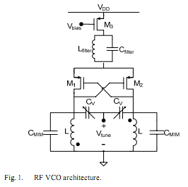
The oscillator is designed to tune from 1.8 GHz to 2 GHz for typical cellular telephony applications. An extended tuning range can be obtained by adjusting the ratio between the varactor capacitance and fixed capacitance in the tank. PMOSFETs...
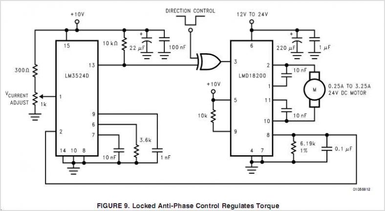
The LMV1090 is a fully analog dual differential input, differential output microphone array amplifier designed to reduce background acoustic noise while delivering exceptional speech clarity in voice communication applications. The LMV1090 effectively preserves near-field voice signals within 4 cm...
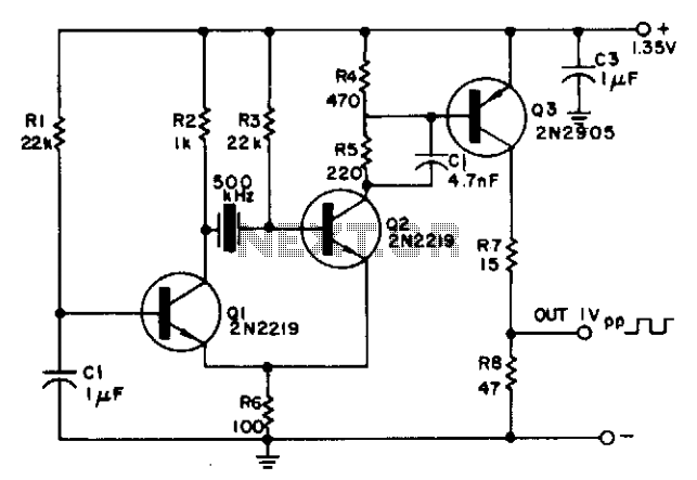
The circuit is powered by a single 1.35 V mercury cell and provides a 1 V square-wave output. The crystal acts as a tuned circuit between transistors Q1 and Q2, which are connected in a common-emitter configuration. Positive feedback...
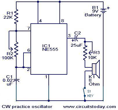
A circuit diagram for generating continuous wave (CW) Morse code is presented here. This circuit is particularly beneficial for individuals interested in practicing Ham Radio. It consists of an astable multivibrator utilizing the NE555 timer. The oscillation frequency of...
One of the simplest methods of metal detecting is through a beat frequency oscillator. The circuit consists of two balanced oscillators: one provides a reference signal, while the other acts as the detector element. The frequency of the reference...
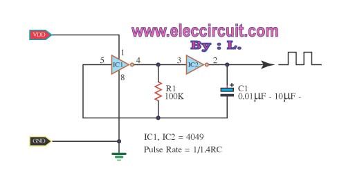
The inverter CMOS digital IC CD4049 is utilized to design a square wave oscillator generator. The CD4049 is a hex inverting buffer, which means it contains six independent inverters that can be used to generate square wave signals. This IC...