
Wien-Bridge Sine-Wave Oscillator
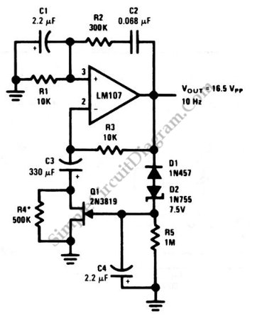
The Wien-bridge oscillator is a type of electronic oscillator that generates sine waves. It consists of an amplifier and a frequency-selective network formed by resistors and capacitors. The circuit is notable for its ability to produce low-distortion sine waves across a range of frequencies.
The key components of a Wien-bridge oscillator include two resistors (R1 and R2) and two capacitors (C1 and C2) arranged in a bridge configuration. The resistors and capacitors are selected to set the desired frequency of oscillation, which can be calculated using the formula:
\[ f = \frac{1}{2\pi R \sqrt{C1 \cdot C2}} \]
where \( R \) is the resistance of R1 and R2 and \( C1 \) and \( C2 \) are the capacitances of C1 and C2.
In addition to the frequency-selective network, the Wien-bridge oscillator employs an operational amplifier (op-amp) configured in a feedback loop. The op-amp provides the necessary gain for oscillation. To ensure stable oscillation, a negative feedback mechanism is integrated into the circuit. This is typically achieved using a light bulb or thermistor, which adjusts the gain automatically. As the gain approaches unity, the circuit stabilizes, preventing oscillations from growing uncontrollably.
The output of the oscillator is a pure sine wave, making it suitable for various applications, including signal generation, audio testing, and function generation in laboratories. The simplicity and effectiveness of the Wien-bridge oscillator make it a popular choice among engineers and hobbyists alike.
In summary, the Wien-bridge sine-wave oscillator is a reliable circuit for generating high-quality sine waves, leveraging negative feedback to maintain stability and control over the gain, thus ensuring consistent performance across its operational frequency range.This is a Wien-bridge sine-wave oscillator circuit. This circuit uses negative-feedback stabilization to make sure the gain won`t go higher than unity to.. 🔗 External reference
Related Circuits

Utilize the Maxim MAX292 switched-capacitor filter integrated circuit to convert a square wave into a sine wave. The operational frequency range of the circuit spans from 5.2282 Hz to 8928.6 Hz when the microcontroller is functioning at a 16-MHz...
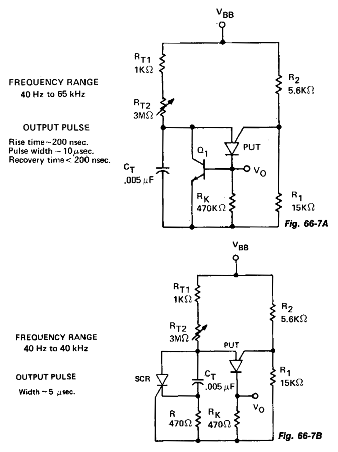
The variable oscillator circuit incorporates active components to discharge the timing capacitor CT, as illustrated in Fig. 66-7A. An alternative method is presented in Fig. 66-7B. The variable oscillator circuit is designed to generate oscillating signals with adjustable frequency characteristics....
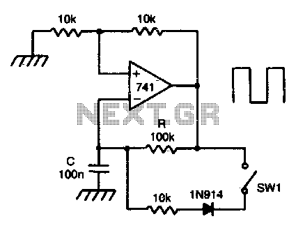
This circuit incorporates a Schmitt trigger and an integrator configured around a single operational amplifier (op-amp). The timing is regulated by an RC network. The voltage at the inverting input tracks the exponential charging of the capacitor within defined...
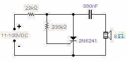
Silicon controlled rectifiers (SCR) can easily oscillate if there is an inductor (a speaker coil in this case) which gives just enough extra voltage to completely switch off the sustain current. In this way a new cycle may start...
This voltage-controlled oscillator circuit is compact and exhibits good linearity. The precision can be better than 0.01% if properly constructed. The circuit provides three different output waveforms: square, triangle, and sawtooth, which are essential for music synthesizers and measurement...
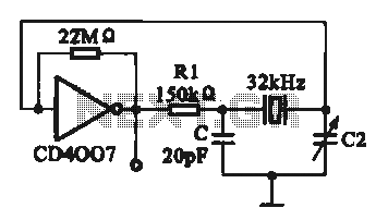
A 32 kHz clock oscillator is essential for digital circuits, as depicted in the schematic. The 32 kHz crystal clock oscillator serves to provide a time reference signal for the digital circuit. It utilizes a CMOS integrated circuit, specifically...