
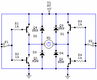
Wilf Rigter`s reversing H-bridge
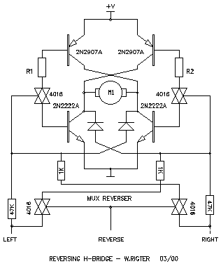
The described H-bridge circuit is a pivotal component in motor control applications, particularly for robotic systems such as two-motor walkers. An H-bridge allows for bidirectional control of DC motors by enabling current to flow through the motor in either direction. This specific variant distinguishes itself by integrating the reversing circuitry directly within the driver, streamlining the design and reducing the complexity typically associated with external control circuitry.
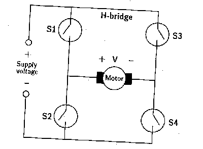
In this configuration, the H-bridge consists of four switches, typically implemented using transistors or MOSFETs, arranged in an 'H' shape. The two motors are connected across the horizontal legs of the 'H', while the vertical legs are connected to the power supply and ground. By controlling the state of the switches, the circuit can reverse the polarity applied to the motor terminals.
For a two-motor walker, the ability to reverse one motor independently allows for more versatile movement patterns. To achieve this, the control logic can be designed to selectively activate the switches associated with the motor that requires reversal. For instance, if one motor is to be reversed, the switches connected to that motor are toggled, while the other motor continues to operate in its original direction.
This approach simplifies the control strategy, as only one motor's phasing needs to be adjusted for directional changes, rather than managing complex control signals for both motors simultaneously. Consequently, the H-bridge variant enhances the efficiency of motor control in robotic applications, facilitating smoother and more responsive maneuvering capabilities.
Overall, this integrated design not only saves space on the circuit board but also reduces the number of components required, leading to a more compact and cost-effective solution for driving dual motors in robotic systems.This H-bridge variant was one of the first in which the reversing circuitry is built into the driver, rather than (as is more-commonly done) into the control circuitry upstream of the driver. This is a handy circuit, though, for 2-motor walkers -- as all that is required to reverse one is to reverse the phasing of one of the motors.
🔗 External reference
Related Circuits
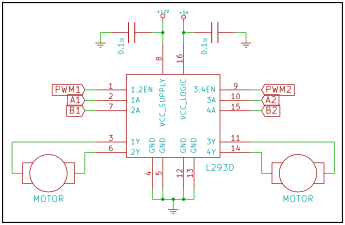
A microprocessor cannot drive a motor directly since it cannot supply enough current. Instead, an interface circuit is required so that the motor power is supplied from another source, with only control signals derived from the microprocessor. This interface...
The H-bridge is a circuit utilized in the electronic control of high-current devices, particularly in applications where the device's polarity needs to be reversed, such as in DC motors. The name derives from the circuit's resemblance to the letter...
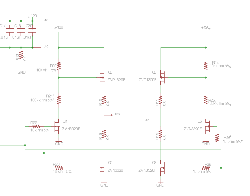
Following the publication of a previous post, some unusual issues were encountered, which required several days to clarify. The main focus was on building a simple Class D amplifier designed to provide an EL panel with a +/- 120V...
The converter utilizes a TinySwitch-III family member (U2, a TNY279PN) to deliver up to 1.8 A of load current to six high-intensity Luxeon LEDs (LXHL series). The output voltage is slightly below the forward voltage drop of the LEDs,...
You have 4 transistors, wired as ON OFF switches. Two signal lines allow you to run the motor in one direction, when reversed, the motor runs in the other direction. It's very straightforward to use and build, but be...
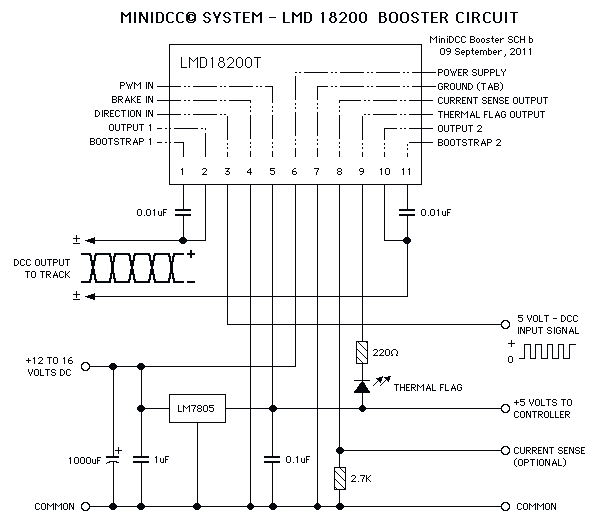
These circuits could be used as the basis for Model Railroad DCC Boosters or PWM motor controllers. The first schematic is for a basic 3 Amp - DCC Booster using the LMD 18200 CMOS, H-Bridge. Included in the design...