
h-bridge circuitry

The H-bridge is a crucial component in motor control applications, allowing for bidirectional control of DC motors. The arrangement of the four switches (transistors) in the H-bridge provides the ability to change the direction of the motor's rotation by altering the state of the switches. The inclusion of flyback diodes is essential for protecting the circuit from voltage spikes generated by the inductive load of the motor, ensuring reliable operation and longevity of the components.
The implementation of pulse-width modulation (PWM) further enhances the functionality of the H-bridge by enabling variable speed control. By rapidly switching the H-bridge inputs on and off, the average voltage and current supplied to the motor can be adjusted, allowing for precise control over the motor's speed. The duty cycle of the PWM signal determines the effective power delivered to the motor, with a higher duty cycle resulting in increased speed.
In practical applications, the H-bridge can be integrated into various control systems, including robotics, automation, and electric vehicles. The use of integrated circuits such as the L293 and L6202 simplifies the design process, as these chips incorporate the necessary circuitry for driving motors while providing built-in protection features.
Overall, the H-bridge circuit is a versatile and effective solution for controlling DC motors, enabling both directional control and variable speed operation through the clever use of switching devices and PWM techniques.A microprocessor cannot drive a motor directly, since it cannot supply enough current. Instead, there must be some interface circuitry so that the motor power is supplied from another power source and only the control signals derive from the microprocessor. This interface circuitry can be implemented by a circuit known as the H-bridge. An H-bridge merely consists of 4 switches connected in topology of an H, where the motor terminals form the crossbar of the H. The diagram on the right shows an H-bridge circuit. In an H-bridge, the switches are opened and closed in a manner so as to put a voltage of one polarity across the motor for current to flow through it in one direction or a voltage of the opposite polarity, causing current to flow through the motor in the opposite direction for reverse direction.
In the circuit shown on the right, if switches S1 and S4 are closed while switches S2 and S3 are open, current will flow from left to right in the motor, or in other words, positive voltage across the terminals. When switches S2 and S3 are closed and switches S1 and S4 are open, current will flow from right to left, reversing the voltage polarity.
If the terminals of the motor are open, the motor will freewheel (vicous braking) and if the terminals are short circuited, the motor will brake(dynamic brake). The switches in the H-bridge circuitry are implemented by power transistors, which can be run of TTL logic.
In TTL logic, high means the switch is closed, and low means open. The H-bridge circuitry is being provided in IC chips like L293, L6202. Consider Fig(a). If the switch opens suddenly, then the current wants to go to zero quickly and dI/dt would be a large negative value. Since the motor is an inductor and V=LdI/dt, the voltage across the motor hass a large negative value.
So, if Vb in fig(b) is much larger than Va in fig(b), we could have voltage spikes. These voltage spikes can cause the switch to arc over and blow up. The solution to this problem is to putwhat is known as a flyback diode in the reverse direction across the inductive load, so that the voltage spike will forward bias the diode, creating a return path for the current. Fig(c) shows how a flyback diode is connected. The H-bridge configuration shown above is fine but it looks like we can only spin the motor at one speed.
To solve this problem, we have to pulse the H-bridge inputs. This leads to the discussion of Pulse Width Modulation. You can click here to read about details on Pulse Width Modulation. 🔗 External reference
Related Circuits
This is a slightly revised version of the 6-transistor H-bridge designed by Mark Tilden and found on the BEAM Tek website (now only available via archive). I encourage anyone interested in H-bridges to read Mark's article, as it gives...
The HandyBoard operates both pads using the positive supply from the battery. When one of the motors is intended to turn, the HandyBoard activates the corresponding pin to 0V. The voltage difference between the two pads causes the motor...
The following circuit illustrates a Bass and Treble Controller Circuit. This circuit is constructed based on the classic Baxandall tone control circuitry. The Bass and Treble Controller Circuit is designed to adjust the low and high-frequency response of audio signals,...
The yellow wires on the far right serve as temporary power connections, allowing battery power to enter through the contact studs located in the large holes that press against the radio's battery terminals. The cable in the lower right...
H-Bridge This circuit drives small DC motors up to about 100 watts or 5 amps or 40 volts, whichever comes first. Using bigger parts could make it more powerful. Using a real H-bridge IC makes sense for this size of...
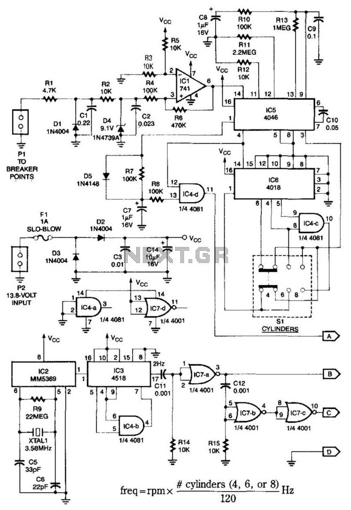
This system is compatible with 4-, 6-, or 8-cylinder automobiles. The timebase generated by IC5 functions as an oscillator that drives counter IC6, which divides the frequency by 6, 4, or 3 for 4-, 6-, or 8-cylinder engines, respectively....