
Window-detector

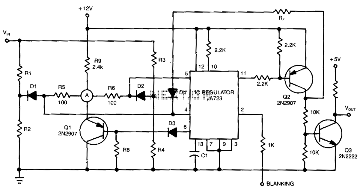
This circuit is designed to monitor an input voltage and control a relay based on specific voltage thresholds. The core component, a 72747 dual op-amp, operates in an open-loop configuration, providing high gain to detect small variations in input voltage. The relay is activated under normal conditions when the input voltage is within the defined range, ensuring that the system remains operational. The use of diodes D1 and D2 serves as a protective mechanism against negative voltage excursions that could inadvertently turn off the transistor Q1, leading to relay deactivation.
The circuit's flexibility allows for customization of the voltage thresholds through external resistors, enabling the user to define the operational parameters according to specific application requirements. The inclusion of protection elements such as diodes D5 and D6 ensures that the integrated circuit remains safeguarded against voltage spikes or negative voltages that could potentially damage it. This makes the circuit robust and reliable for various applications where monitoring and controlling relay states based on voltage levels is essential.
Furthermore, the design allows for the adjustment of input voltage levels through the use of RV3, accommodating scenarios where the desired threshold voltages exceed the supply voltage limits. The overall design is efficient, allowing for a wide range of input voltages while maintaining the integrity and functionality of the relay control system. The circuit's maximum supply voltage rating of 30 V ensures compatibility with standard power supply configurations, making it suitable for integration into various electronic systems.This circuit de-energizes a normally energized relay if the input voltage goes above or below two individually set voltages. The transistor driving the relay is normally turned on by R4, so the relay is normally energized. Ifthe cathode of Dl or D2 is taken negative, Ql will turn off and the relay will de-energize. The IC is a 72747 dual op amp used without feedback, so the full gain of about lOOdB is available. The amplifier output will thus swing from full positive to full· negative for a few m V change at the input.
The relay is therefore only energized if llN is between VUL and VLL. The two limits can be set anywhere between the supply rails, but obviously VuL must be more positive than "LL. If Vrn can go outside the supply rails, DS, D6, and RS should be added to prevent damage to IC1. If VuL and "LL are required to be outside the supply rails, llN can be reduced by RV3. The supplies can be any value, providing that the voltage across them is not more than 30 V. 🔗 External reference
Related Circuits

This simple window detector utilizes half of a 7400 quad NAND gate along with four resistors, selected to ensure that the voltage at point A exceeds the voltage at point B for any input voltage. When no input is...
The detector circuit compares the output voltage of two separate voltage dividers with a fixed reference voltage. The resultant absolute error signal is amplified and converted to a logic signal that is TTL compatible. The described detector circuit serves as...
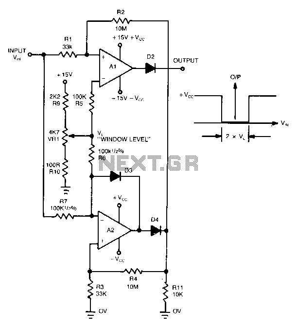
This novel window detector utilizes only two operational amplifiers. The width of the window can be adjusted using a 4.7 kΩ potentiometer. The described window detector circuit employs two operational amplifiers (op-amps) to create a functional and efficient signal conditioning...