
Window-detector
The described detector circuit serves as a fundamental component in various electronic applications, particularly in systems requiring voltage monitoring and comparison. The circuit operates by utilizing two voltage dividers, which are typically composed of resistors arranged in series. Each voltage divider provides a proportional output voltage based on the input voltage applied across it.
The first voltage divider outputs a voltage that reflects a specific portion of the input, while the second divider is designed to output a voltage that corresponds to a predetermined reference level. The comparison between these two voltages is critical, as it determines whether the input voltage is above or below the reference voltage.
The core of the circuit includes a differential amplifier or comparator, which assesses the difference between the two voltage outputs. This comparison generates an error signal, representing the absolute difference between the measured voltage from the dividers and the fixed reference voltage. The error signal is then subject to amplification, ensuring that even minor discrepancies can be detected and processed effectively.
Following amplification, the error signal is converted into a logic signal compatible with Transistor-Transistor Logic (TTL) standards. This conversion is essential for interfacing with digital circuits, as TTL logic levels are widely used in modern electronic systems. The output logic signal can then be used to trigger further actions, such as activating alarms, controlling relays, or interfacing with microcontrollers for more complex decision-making processes.
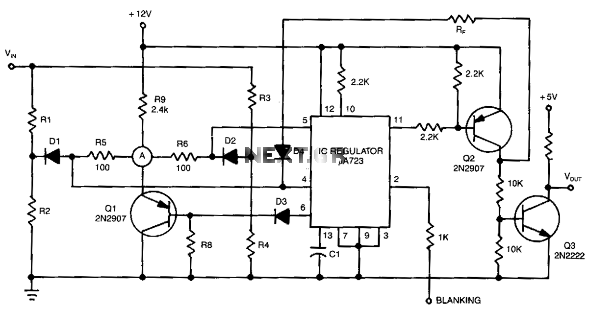
This detector circuit is versatile and can be implemented in various applications, including battery management systems, voltage monitoring for power supplies, and feedback control systems in automated processes. Its ability to provide accurate voltage comparisons and convert those comparisons into usable logic signals makes it an invaluable tool in electronic design.The detector circuit compares the output voltage of two separate voltage dividers with a fixed reference voltage. The resultant absolute error signal is amplified and converted to a logic signal that is TTL compatible. 🔗 External reference
Related Circuits

This simple window detector utilizes half of a 7400 quad NAND gate along with four resistors, selected to ensure that the voltage at point A exceeds the voltage at point B for any input voltage. When no input is...
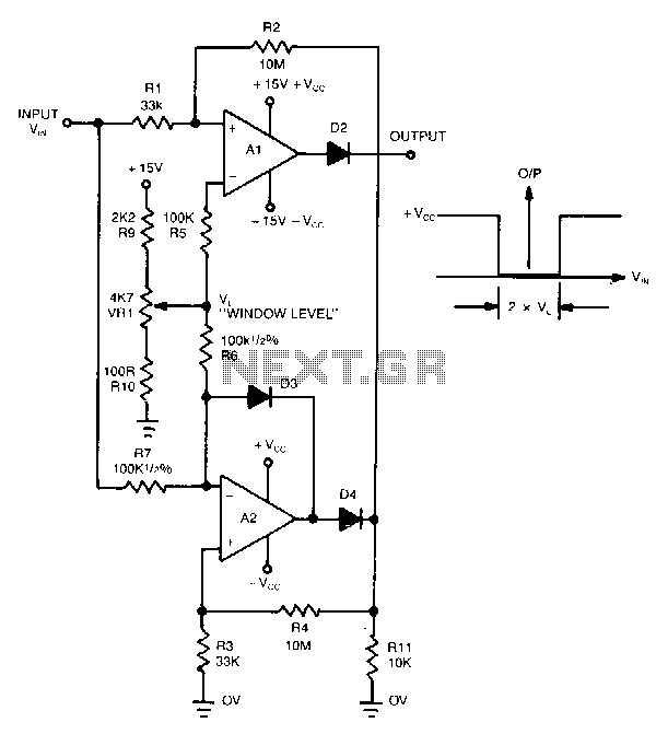
This novel window detector utilizes only two operational amplifiers. The width of the window can be adjusted using a 4.7 kΩ potentiometer. The described window detector circuit employs two operational amplifiers (op-amps) to create a functional and efficient signal conditioning...
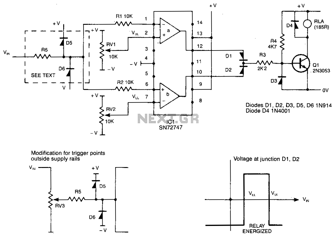
This circuit de-energizes a normally energized relay if the input voltage exceeds or falls below two individually set voltages. The transistor driving the relay is typically activated by resistor R4, keeping the relay energized. If the cathode of diodes...