
Windspeed Indicator Circuit With LM7805 IC
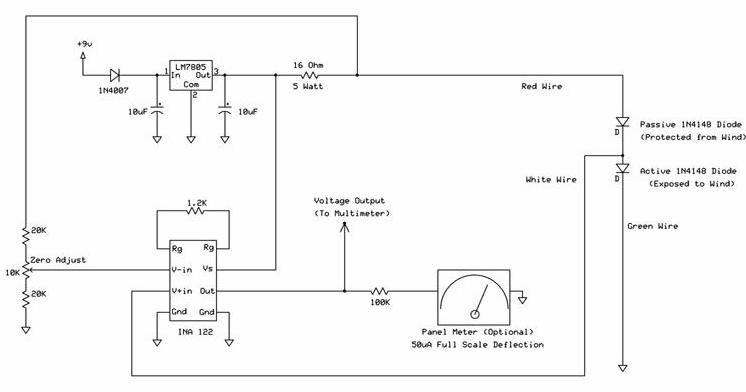
The wind speed indicator circuit is designed to measure and display wind speed in a user-friendly manner. The core of the circuit is the LM7805 voltage regulator, which ensures that the circuit receives a stable 5 VDC power supply. This is critical for the accurate operation of the sensing and display components.
The circuit typically incorporates a wind speed sensor, such as a small anemometer, which converts wind speed into an electrical signal. This sensor is connected to an analog-to-digital converter (ADC) if a digital display is utilized, allowing the microcontroller to interpret the sensor's output. The microcontroller processes the input data and drives a display, which may be an LCD or LED screen, to show the wind speed in real-time.
The 9 VDC supply serves as the input voltage for the LM7805 regulator, which steps down the voltage to 5 VDC. This regulator is chosen for its simplicity and reliability, making it suitable for various applications in electronic circuits. Additional components may include resistors, capacitors, and diodes, which help stabilize the voltage and protect the circuit from potential damage due to voltage spikes.
Overall, the wind speed indicator circuit is a practical application of basic electronic principles, combining sensors, microcontrollers, and voltage regulation to provide a functional and informative device for measuring wind speed.the following circuit shows about Windspeed Indicator Circuit. Features: down to a constant 5 VDC by the LM7805 voltage regulator, 9 VDC supply .. 🔗 External reference
Related Circuits
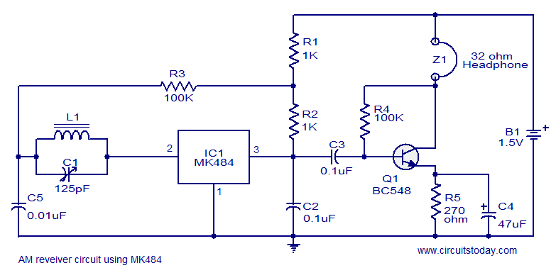
A cost-effective and straightforward AM receiver circuit utilizing the MK484 integrated circuit. The circuit requires minimal external components and operates within a frequency range of 150 kHz to 3 MHz. The MK484 AM receiver circuit is designed for simplicity and...
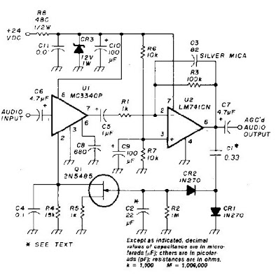
An audio signal applied to VI is passed through the operational amplifier 741, U2. After being amplified, the output signal V2 is sampled and applied to a negative voltage doubler/rectifier circuit composed of diodes CR1 and CR2, along with...
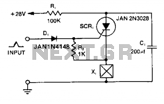
Capacitor C1 is charged to +28 V through resistor R1 and stores energy for firing the squib. A positive pulse of 1 mA applied to the gate of SCR1 will cause it to conduct, discharging C1 into the squib...
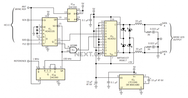
The physical transmission medium for the 429 standard is 78Ω shielded, twisted-pair cable that uses a complementary, differential bipolar RZ (return-to-zero) waveform. The voltages are the net differentials that the biphase drive develops: For example, the differential is 10V...
The LED Metronome is a contemporary version of a traditional device that is essential for music teachers, students, and composers. This circuit employs 12 LEDs to replicate the swinging motion of a pendulum, along with a speaker connected to...
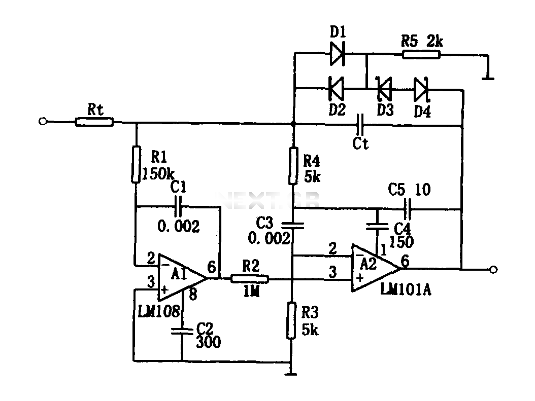
The high-speed integrating circuit is designed with an integration time constant circuit, RtCt, which offers a wide range. When the integrating capacitor Ct is not considered, A2 functions as a positive feedback compensation broadband AC amplifier. The negative feedback...
Warning: include(partials/cookie-banner.php): Failed to open stream: Permission denied in /var/www/html/nextgr/view-circuit.php on line 713
Warning: include(): Failed opening 'partials/cookie-banner.php' for inclusion (include_path='.:/usr/share/php') in /var/www/html/nextgr/view-circuit.php on line 713