
High-speed integrator circuit (LM101A, LM108)
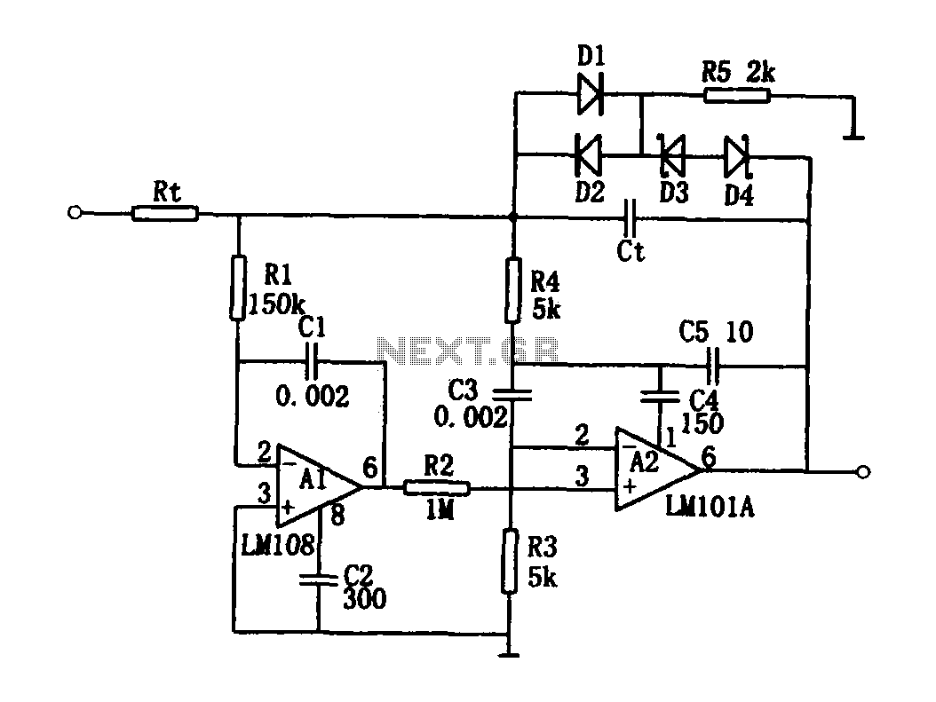
The high-speed integrating circuit utilizes a combination of operational amplifiers and passive components to achieve rapid signal integration with a broad frequency response. The integration time constant, determined by the product of resistors and capacitors (RtCt), is critical in defining the circuit's performance characteristics. The circuit employs operational amplifier A2, which acts as a broadband AC amplifier with positive feedback, enhancing its gain while maintaining stability through the feedback network.
The integration process is facilitated by the coupling of the integrating capacitor Ct with the feedback loop of A2. The design ensures that both low-frequency and DC components of the input signal are effectively integrated. The inclusion of resistor R2 in the inverting input path of both amplifiers A1 and A2 contributes to the circuit's high-speed performance, enabling it to handle smaller input bias currents efficiently.
To ensure stability during operation, the positive feedback is compensated by the network formed by resistors R4, C4, and C5. This compensation network mitigates the risk of oscillation, allowing the circuit to maintain a steady output in response to varying input signals. The clamping mechanism, realized through diodes D1, D2, D3, and D4, along with Zener diodes and resistor R5, regulates the output voltage levels, providing protection against voltage spikes and ensuring reliable operation.
The precise selection of the Zener diodes is crucial, as they must exhibit closely matched stable voltage characteristics to maintain the integrity of the clamping action. This careful design consideration enhances the overall robustness of the high-speed integrating circuit, making it suitable for applications requiring rapid signal processing and integration.As shown for the high-speed integrating circuit. The integration time constant circuit RtCt have a greater range. If you do not consider integrating capacitor Ct, A2 is a positive feedback compensation broadband AC amplifier. A2 negative feedback loop coupled capacitance Ct, constitute an integrator. Due to the low frequency and DC portion of the input signal by A1 and A2 of the resistor R2 is added to the same inverting input constitutes a high speed integrator, and may allow smaller input bias current. Positive feedback is compensated by the R4, C4 and C5 constitute. Diodes D1 and D2, D3 and D4 Zener diode and a resistor R5 composed clamp. Two Zener diode should be approximately equal stable voltage.
Related Circuits
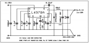
A small-sized and easy-to-build 5V 10A power supply circuit is being sought. This circuit utilizes the L4970A integrated circuit as a 10A switching regulator. It is essential that the power supply input can handle a current of 10A to...
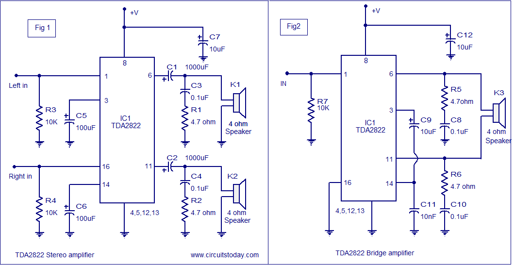
The TDA2822 audio amplifier circuit provides 1.35W output into a 4-ohm speaker when powered by a 6V supply. It supports both bridge and stereo modes and operates within a supply voltage range of 3V to 15V, making it suitable...
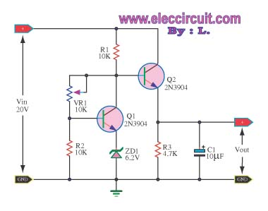
This circuit maintains a constant voltage, with an adjustable output voltage. It serves to reduce the input voltage while keeping the voltage constant. The amplifier model used is the Q1 2N3904 in a common-emitter configuration. This configuration allows the...
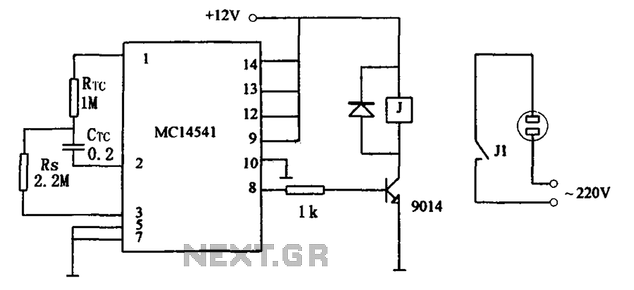
The circuit illustrated in FIG MC14541 is a straightforward timing circuit utilizing the MC14541 integrated circuit (IC). By adjusting the parameter map, the timing can be set for a duration of 3 hours, with options to select various RTC,...
There are digital and analog methods that can be used to compensate for the nonlinearity of a PT100 RTD. Digital linearization can be implemented through various techniques. Compensation for the nonlinearity of a PT100 RTD (Resistance Temperature Detector) is essential...
There was difficulty in understanding that the Source pin connects to low voltage (source of electrons) and the Drain pin connects to high voltage (absorbs electrons). This concept is fundamental to basic electricity, but it required some time to...
Warning: include(partials/cookie-banner.php): Failed to open stream: Permission denied in /var/www/html/nextgr/view-circuit.php on line 713
Warning: include(): Failed opening 'partials/cookie-banner.php' for inclusion (include_path='.:/usr/share/php') in /var/www/html/nextgr/view-circuit.php on line 713