
wire three-way circuit between two buildings with only 3 conductors

The circuit design described involves a three-way switch configuration that allows for the control of two porch lights from multiple locations. In this case, the switches in the garage and kitchen create a functional circuit for the porch lights, which is essential for maintaining convenience and safety in the outdoor lighting system. The use of a 10-3 Romex cable to provide power from the main service panel ensures that adequate current capacity is available, as it is rated for 30 amps, which is suitable for lighting circuits.
The proposed wiring method involves connecting the black wire from a new Romex cable to the common terminal of the three-way switch in the garage. This connection is essential as it allows the switch to control the porch light directly. The white wire from the additional Romex cable, which is intended to provide a neutral connection in the garage's load center, must be correctly identified and connected to avoid any confusion with the switched leg of the circuit.
In addition, the grounding strategy proposed involves temporarily connecting ground wires to the neutral bar in the garage until a new load center can be installed. This approach is not ideal, as it can create potential safety hazards, including the risk of overloading the neutral wire and creating a shock hazard. It is advisable to prioritize the installation of a properly grounded load center in the garage to ensure compliance with safety standards and to mitigate risks associated with improper grounding.
Regarding the concern about the GFCI outlet, if the power source is taken from the load side, it is crucial to ensure that the neutral wire returning from the garage light is correctly routed back to the GFCI. If the neutral does not return through the GFCI, it may cause the GFCI to trip, leading to an interruption in service. It is essential to follow the National Electrical Code (NEC) guidelines to ensure that the circuit is safe and functional, especially given the complexities of the existing wiring and the modifications proposed.I am rewiring my entire house after a major malfunction of two antique knob and tube circuits. I`m up against a challenge with some outdoor lights. Here`s the situation: I have a detached garage. It has a porch light over the service door, and it works on a pair of three way switches located in the garage and in my kitchen. The porch light over th e kitchen door also works with this garage light - they are both controlled by the same 3 way switches. I`m a really big fan of this setup, and I hope to save it. The garage is powered by an underground 10-3 romex cable connected to a 2 pole 30 amp breaker in my brand new 200 amp main service panel in my basement.
It goes to an old QO service panel in the garage that has no main breaker and no ground bar. There is also a 12-3 romex cable going to the garage to make the three way switches between the two buildings function. Neither cable has a ground wire. Both cables are buried under my blacktop driveway and not in conduit, so they are so hard to replace that let`s just assume it`s impossible.
I know I need to replace the load center in my garage with a new, grounded unit. Remember, I`m rewiring a whole, enormous old house built in 1878, so getting the lights back on is first priority - I`ll get to the garage when the house is done. My question concerns the 3 way circuit controlling those two porch lights. It seems like it shouldn`t work with only 3 conductors travelling between the switches and lights on both ends, but somebody did all kinds of janky stuff with the old knob and tube wiring to make it work (It wasn`t me!).
I`m thinking about doing something that maybe isn`t quite as janky as that, but I need to know whether it`s safe. There is no building inspector where I live, so just go by National Codes and personal experience I guess.
Here is a diagram of what I`m thinking about doing. Basically I would run a fairly normal 3 way circuit, except that when it gets to the switch in the garage I would wire nut the black wire from a piece of romex to the wire coming off the common and run it to my porch light. Then I would take another piece of romex and use the white wire in it to get a neutral connection in the garage`s load center for the garage light.
Ground wires in the garage would just run to the neutral bar until I get a new load center out there. Grounds in the basement would be wired properly to my new load center in there. Between the switches there would be no ground since I can`t add one to the underground cable. Is it safe If the "power source" is the "load" side of a GFCI outlet, will it constantly trip since the current on the neutral from that garage light isn`t returning through it All help is appreciated.
🔗 External reference
Related Circuits
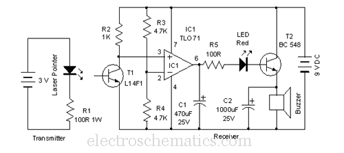
This laser door alarm operates by detecting the interruption of a laser beam. A low-cost laser pointer serves as the light source. When an individual crosses the path of the laser beam, it triggers the alarm. The laser door alarm...
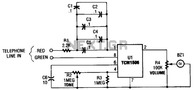
The circuit utilizes the TCM1506 ring detector/driver integrated circuit, which is a monolithic IC designed to replace mechanical bells in telephones. It is powered and activated by the telephone line's ringing signal, which ranges from 40 to 150 V...

A charged capacitor C3 and a momentary pushbutton switch S2 are utilized to temporarily activate relay RE2. The battery being charged powers the relay to maintain its closed state. Additionally, S2 can energize the relay even if the battery...
This circuit is designed to power a lamp or other appliance for a specified duration of 30 minutes, after which it automatically turns off. It is particularly useful for nighttime reading, as it can turn off a bedside lamp...
Portable loads such as video cameras, halogen flood lights, electrical irons, hand drills, grinders, and cutters are powered by connecting long 2- or 3-core cables to the mains plug. Due to prolonged usage, the power cord wires are subjected...
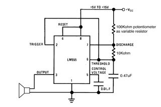
Setting the 555 timer in astable mode results in a continuous series of output pulses. The 555 timer IC, when configured in astable mode, operates as an oscillator, generating a square wave output. This configuration does not require any...