
wireless FM bug

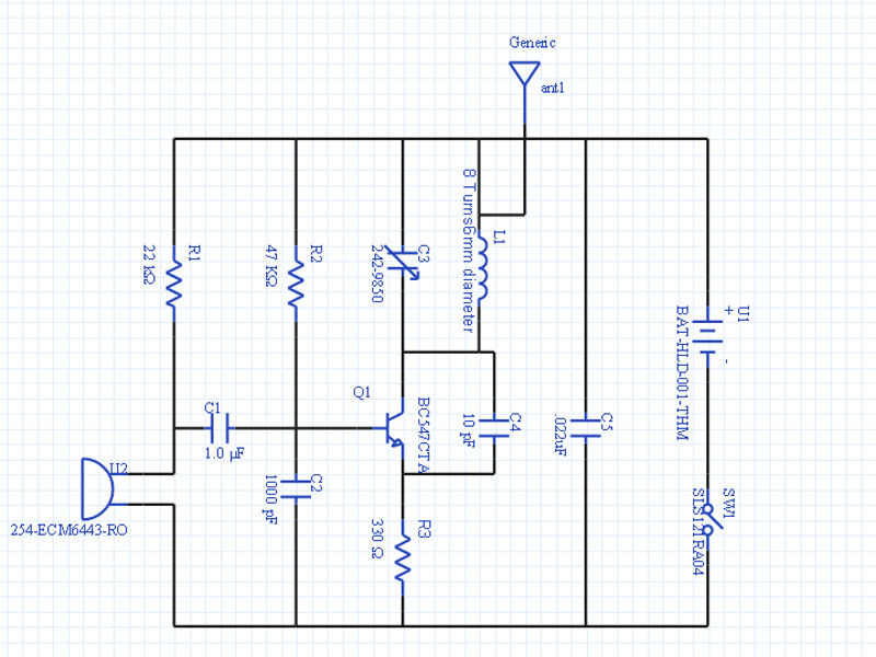
The VHF FM Wireless Microphone transmitter circuit is designed to operate within the very high frequency (VHF) band, utilizing wideband frequency modulation. The primary components of the circuit include an electret condenser microphone, a transistor for amplification, and a tuned circuit consisting of an inductor and capacitor that determines the transmission frequency. The circuit's simplicity makes it an ideal project for educational purposes, particularly for engaging children in radio technology.
In the construction of the circuit, two variations are available: a coil version and a printed circuit board (PCB) version. The coil version requires a 1/4 inch diameter coil, which can be wound on a drill bit, while the PCB version integrates the coil directly onto the board, eliminating the need for manual winding. For the antenna, a length of insulated wire approximately 60 cm is utilized, connected to a one-turn tapping of the coil to optimize transmission.
It is recommended to use tinned copper wire for the tuning coil to facilitate easier soldering, particularly for beginners who may struggle with enamel-coated wire. The circuit is designed to be powered from a standard battery, and the output can be connected to any VHF FM receiver, allowing for versatile applications.
For those wishing to adapt the circuit for specific uses, such as connecting to the headphone socket of an HF rig, modifications can be made by removing a 4.7 kΩ resistor and reversing a 1 µF capacitor. The transmitter is capable of achieving a range of approximately 100 meters, which can be adjusted by changing the emitter resistor value.
It is important to note that the circuit may exhibit sensitivity to changes in the antenna or power supply connections, leading to frequency instability. This characteristic is typical of such circuits and can be mitigated by adding an antenna buffer or amplifier, although this may complicate the design for novice builders. Overall, this project serves as an engaging introduction to radio technology while providing practical experience in electronics assembly.This project is a miniature, VHF FM (wideband) Wireless Microphone transmitter of the type that are commonly refered to as BUG's. Note that "BUGS" are illegal but "Wide-Band Frequency Modulation Wireless Microphones" (WBFMWMs) are not, as so many people have told me (including the RSGB!).
Besides, the AF sensitivity of this transmitter prevents it from being an effective bug for eaves-dropping! I personally use one of these WBFMWMs plugged into my HF rig headphone socket so that I can "earwig" QSO's and nets when sitting on the toilet, washing the dishes, bringing in the coal, etc.
I know from experience that this project can be used to stimulate interest in Radio in older children, and this was also one of the projects given to a group of scouts and girl- guides to construct. Surprisingly, I found the girls made a better job of soldering than the boys! The circuit is very simple and needs no explanation for construction although the kids needed some guidance when soldering.
The coil version uses a 1/4" (4mm) diameter coil wound on a drill bit, although the PCB version has the coil fabricated on the PCB itself. A simple piece of insulated wire about 60 cm (2 feet) was fine for the antenna, and is connected to a 1-turn tapping of the coil.
Use tinned copper wire for the tuning coil and not the enamelled wire for kids to build. It is much easier for them to solder the antenna, without "mashing-up" the coil, whilst trying to remove the enamel. The PCB version is ideal for the kits as there is no coil to wind, see the photographs on this page. If you wish to use the BUG (sorry!) FM Wireless Microphone from the headphone socket of an HF rig, then delete the 4K7 resistor (and reverse the 1uf capacitor).
The circuit shown is for an "Electret" condenser microphone. The transmitter may be received by any VHF FM radio, but the pocket radio I use about the house was free with WEETABIX box-tops a few years ago. The unit should have a range of at least 100 meters (250 feet) but increase the "220 ohm" emitter resistor to 1K to reduce the range (if you think that little Johnny could plant it in you and your wife's bedroom).
Here is a table to give you an idea of the performance of the BUG (sorry! for get I said that!) FM Wireless Microphone Transmitter: NOTE: Since the antenna is coupled directly to the tuned circuit coil, the final frequency of the oscillator will vary if the antenna or the battery is touched. This could make this little circuit seem unstable. This is a normal feature of this type of circuit. To avoid this you will need to add an antenna buffer/amplifer but this only adds to the complexity - not exactly ideal for beginners.
See my FM wireless microphone V5 if you need a more stable circuit. 🔗 External reference
Related Circuits
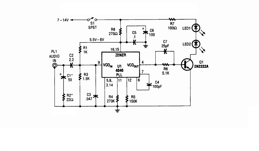
Wireless infrared headphone transmitter. Audio input from PL1 frequency modulates the voltage-controlled oscillator (VCO) section of a 4046 phase-locked loop (PLL) chip. The VCO output drives Q1, a switching transistor, which in turn drives two infrared (IR) LEDs. The wireless...

The circuit depicted utilizes the UPC1651 integrated circuit produced by NEC Corporation of Japan. It offers high gain and stability, ensuring optimal performance for microphones. The design incorporates an FM transmitter circuit. The system employs a flexible antenna measuring...

The infrared (IR) region is free from radio interference but can experience disruptions from incandescent lamps, fluorescent lamps, stray reflections, and other sources. A straightforward solution to this issue is to generate a carrier by modulating the IR radiation...

4 Channel 433MHz Wireless RF Remote Control Kit with a range of 200 meters. This RF remote control offers an extended range of up to 200 meters (650 feet) and is versatile for controlling various devices. The 4 Channel 433MHz...

XBee modules are among the most powerful wireless communication modules available, known for their ease of configuration and use. Their cost ranges from Rs.1000 to Rs.2500, depending on the range and other specifications. It is common for users to...
The schematic below illustrates a simple circuit that is straightforward to construct. One aspect that is not clearly represented in the schematic is the location of certain components. This circuit design comprises a basic arrangement of electronic components, typically including...