
FM Listening Bug Kit

This circuit design comprises a basic arrangement of electronic components, typically including resistors, capacitors, and possibly diodes or transistors, depending on the specific application. The simplicity of the circuit allows for ease of assembly, making it suitable for beginners or for educational purposes in electronics.
Key components may include a power source, such as a battery or power supply, which provides the necessary voltage and current for operation. Resistors are often used to limit current flow, while capacitors can be utilized for smoothing voltage fluctuations or for timing applications. If diodes are included, they may serve to protect the circuit from reverse polarity or to rectify AC signals into DC.
The schematic should clearly indicate the connections between these components, often represented by lines that denote electrical pathways. Each component will be labeled with its respective value, such as resistance in ohms for resistors or capacitance in farads for capacitors, ensuring that the builder can accurately replicate the circuit.
Additionally, it is crucial to pay attention to the orientation of polarized components, such as electrolytic capacitors and diodes, as incorrect placement can lead to circuit failure. The layout should facilitate a logical flow of current, ensuring that all components are connected in a manner that fulfills the intended function of the circuit.
Proper assembly techniques, such as soldering connections cleanly and securely, will contribute to the reliability and longevity of the circuit. Testing the circuit with a multimeter before powering it on can help identify any potential issues in the assembly process, ensuring that the final product operates as designed.As you can see in the schematic below this is a very simple circuit and will be an easy build. On thing the Schematic doesn`t convey very well is wher.. 🔗 External reference
Related Circuits

Many cordless phones are still analogue and use the frequency from 30-50MHz. The signal is FM-modulated and can easily be picked up with any FM receiver. An FM receiver that can be adjusted within this frequency range is presented....
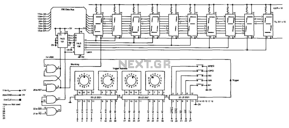
Getting microprocessor designs to function correctly is often challenging, particularly when both the software and hardware are unfamiliar. The typical method involves executing test routines that target memory and I/O without relying on their proper operation. However, any miswiring...
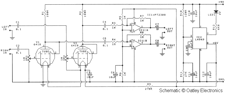
Oatley Electronics, located in New South Wales, Australia, offers several kits based on the Raytheon JAN 6418 sub-miniature valve (tube). The K272A Stereo Tube Preamplifier - Headphone Driver kit, priced at $27 AU, is one such kit. (Note: The...
This Mini FM Bug Detector is basically a broad-band receiver. It picks up the complete band from below 80MHz to 150MHz and almost anything that transmits in that band will be detected. If a bug with a sensitive microphone...
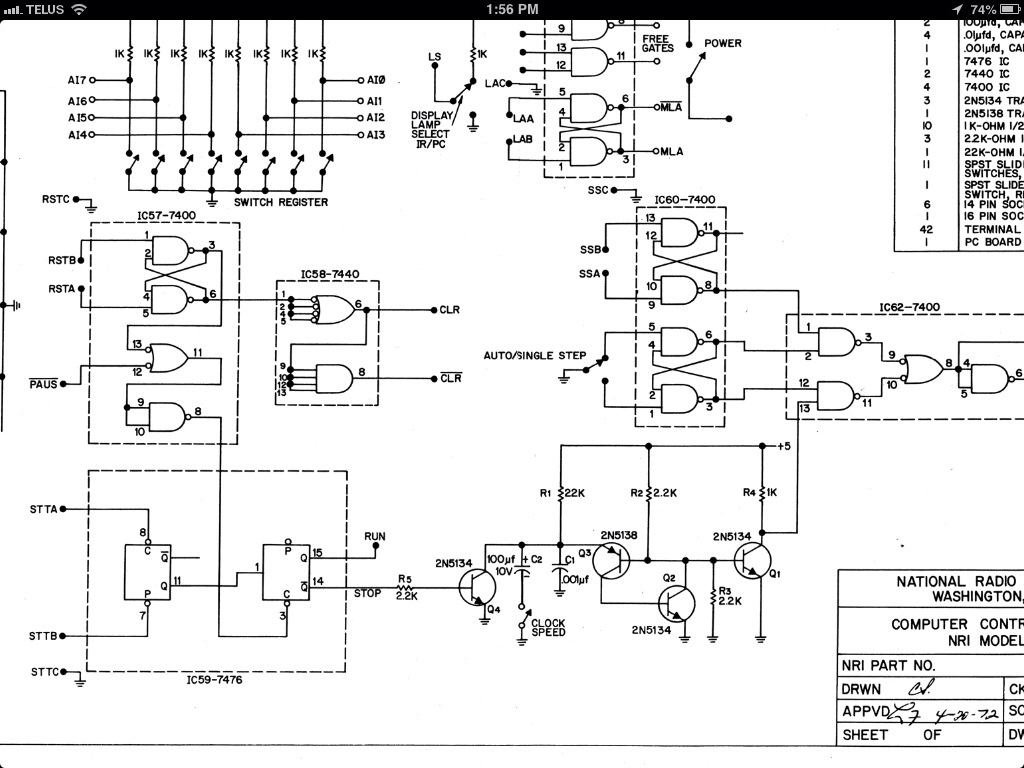
Progress has been made on the project. Recently, a 6 kHz oscillator was constructed using a 555 timer to generate a clock signal for injection into the 832 unit. The output can be observed on an oscilloscope, and an...
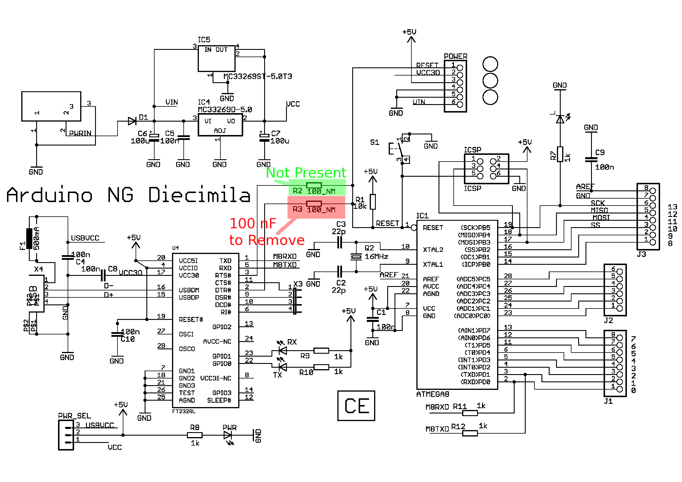
This article discusses the Diecimila; however, there is a newer article that focuses on the Duemilanove. A shift in topic is presented, providing instructions on how to modify an Arduino board to enable useful functions such as debugging. The...