
Wireless IR headphone transmitter
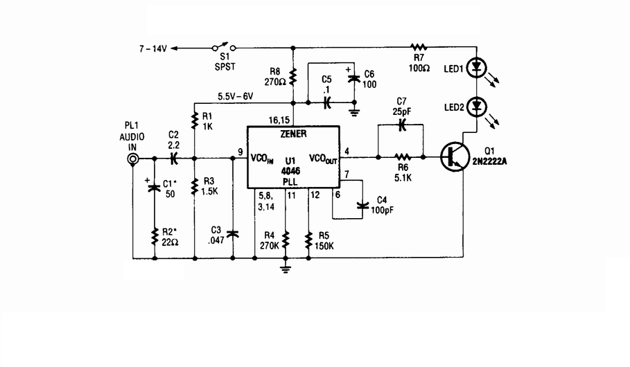
The wireless infrared headphone transmitter operates by converting audio signals into modulated infrared light signals. The audio input is connected to PL1, which serves as the input jack for audio sources. This signal is fed into the VCO section of the 4046 PLL chip, where it is frequency modulated. The VCO generates a signal that varies in frequency according to the amplitude of the audio input.
The output of the VCO is then used to control Q1, a switching transistor. This transistor acts as an electronic switch, allowing the modulated signal to drive two infrared LEDs. The modulation of the current through these LEDs corresponds to the audio input, resulting in an infrared light signal that carries the audio information.
The two IR LEDs are positioned to emit infrared light in a direction where the receiving headphones can capture the signal. The headphones contain a photodetector that demodulates the IR light back into an audio signal, allowing the user to hear the transmitted audio wirelessly.
This design ensures efficient transmission of audio signals over a short distance, making it suitable for applications such as home theater systems or personal audio devices. The use of infrared light for transmission provides a line-of-sight communication method, minimizing interference from other electronic devices.Wireless IR headphone transmitter. Audio input from PL1 frequency modulates the VCO section of a 4046 PLL chip. The VCO output drives Q1, a switching transistor. Q1 drives two IR LEDs. The. 🔗 External reference
Related Circuits
The circuit was constructed using a few components powered by a 9 V battery for sensing the presence of bugs transmitting within the frequency modulation range. Frequency Modulation (FM) transmits its signal or information over a carrier wave by...
This is a TMP01 Temperature Sensor Transmitter circuit. This circuit is used in industrial environments to transmit the signal differentially on a wire pair. The TMP01 Temperature Sensor Transmitter circuit is designed to provide accurate temperature measurements in industrial settings,...
This circuit is a wireless car alarm system constructed using two modules: a transmitter module and a receiver module. It operates on FM radio waves and is suitable for vehicles with a power supply of 6-12VDC. A voltage stabilizer...
For all measurements with the oscilloscope, use the oscilloscope probe with a 10:1 attenuation to minimize measurement errors caused by the capacitance of coaxial cables and the input resistance of the oscilloscope. Problem 1 aims to simulate, build, and...
This operational amplifier (opamp) is available at a low cost. The AD8099 is a very fast opamp with a slew rate of 1600 V/µs and features high-impedance inputs with low input capacitance. Its bandwidth is sufficiently large that at...
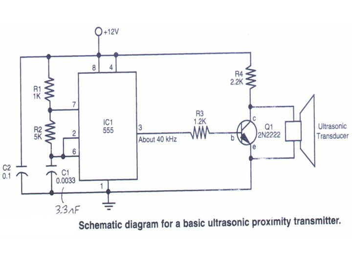
This section provides step-by-step instructions along with images for constructing an Ultrasonic Proximity Transmitter. Due to the simplicity of the circuit, only a schematic for the sensor is presented here. The objective of this tutorial is to assist others...