
Bedside Lamp TimerCircuit Based On The CD4060 IC

The Bedside Lamp Timer Circuit utilizes the CD4060 IC, which is a versatile component capable of generating a range of timing intervals. The circuit is designed to control the illumination of an LED, which serves as an indicator or as part of a bedside lamp setup. When activated, the circuit allows the LED to remain lit for about 25 seconds before automatically turning off, providing a convenient way to light a room without the need for manual operation.
The CD4060 is a 14-pin IC that includes an oscillator and a binary counter. In this application, the oscillator generates a clock signal, which is fed into the binary counter. The counter is configured to count a specific number of cycles before triggering the output to turn off the LED. External components such as resistors and capacitors are connected to the CD4060 to set the timing interval. The values of these components can be adjusted to modify the duration for which the LED remains illuminated.
For practical implementation, the circuit may include a switch to activate the timer and a power source, typically a low-voltage DC supply. The LED is connected to the output pin of the CD4060, ensuring that it receives the necessary current to illuminate. The circuit can be housed in a suitable enclosure, making it a practical addition to bedside lighting solutions.
This timer circuit not only enhances convenience but also contributes to energy savings by ensuring that the lamp is not left on indefinitely. Overall, the Bedside Lamp Timer Circuit based on the CD4060 IC is a practical and efficient solution for automated lighting control.The following circuit shows about Bedside Lamp Timer Circuit Diagram. This circuit based on the CD4060 IC. Features: LED illuminates for around 25 .. 🔗 External reference
Related Circuits
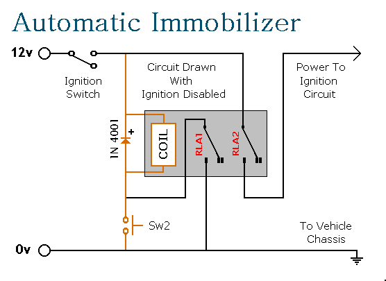
This circuit features automatic exit and entry delays, an optional instant alarm zone, an optional intermittent siren output, and an automatic reset. By adding external relays, the vehicle can be immobilized and the lights can be flashed. The alarm...
For several years, a rear fog lamp has been mandatory for trailers and caravans to enhance visibility in foggy conditions. When the fog lamp is activated, the fog lamp of the towing vehicle must be turned off to prevent...
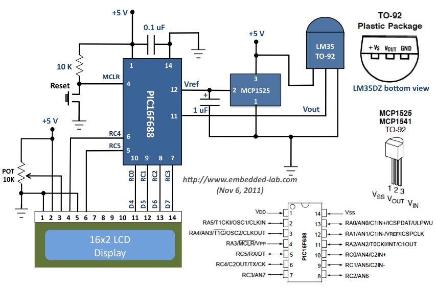
This document outlines a revised version of an LM35-based digital thermometer project previously shared. While it is a straightforward project, it remains popular among beginners learning about microcontrollers. The initial version contained a flaw, as some readers noted that...

For those unfamiliar with electronics, it is important to understand that an oscilloscope essentially has a single timebase that moves the spot horizontally from left to right with consistent intensity. The vertical deviation corresponds to the input voltage. It...

The circuit operates on a 220V AC input, which is stepped down by a buck converter using resistor R3. The output voltage is rectified by a VDI rectifier and filtered through VD2 and capacitor C3, providing approximately 3.9V DC...
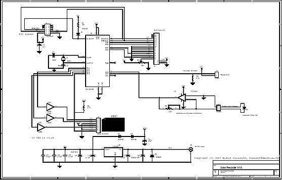
A device for measuring daily insolation has been developed. The device is constructed using a PIC18F458 microcontroller and a 128MB Multimedia Memory Card (MMC). The insolation measurement device leverages the capabilities of the PIC18F458 microcontroller, which is known for...
Warning: include(partials/cookie-banner.php): Failed to open stream: Permission denied in /var/www/html/nextgr/view-circuit.php on line 713
Warning: include(): Failed opening 'partials/cookie-banner.php' for inclusion (include_path='.:/usr/share/php') in /var/www/html/nextgr/view-circuit.php on line 713