
Wireless Switch Circuit PCB
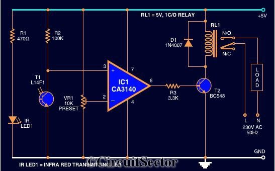
This wireless relay switch circuit utilizes the CA3140 operational amplifier, which is configured to amplify the small current changes induced by the phototransistor when it detects interruptions in the infrared beam. The infrared LED emits a continuous beam of infrared light, which is directed towards the phototransistor. When a hand or object interrupts this beam, the phototransistor's conductivity changes, resulting in a variation in its output signal.
The circuit includes a power supply, typically a battery or DC source, which powers the infrared LED and the operational amplifier. The phototransistor is connected to the input of the CA3140, which is set up in a comparator configuration. When the infrared light is uninterrupted, the phototransistor remains in a non-conductive state, and the output of the CA3140 stays low, keeping the relay in the off position. Conversely, when the beam is interrupted, the phototransistor conducts, causing the voltage at the input of the CA3140 to rise above a certain threshold. This triggers the output of the CA3140 to switch high, activating the relay and turning on the connected appliance.
The relay acts as a switch that can handle higher voltages and currents, allowing it to control various devices safely. Additional components such as resistors and capacitors may be included in the circuit to stabilize the operation and prevent false triggering from ambient infrared sources or noise.
Overall, this wireless relay switch circuit offers a convenient and efficient means to control home appliances through simple hand gestures, enhancing user interaction and accessibility.The circuit diagram shown here is a very sensitive wireless relay switch that can be used to control the working of home appliances like flush system, hand dryer or else. The wireless switch described here needs no remote control for its working. You only want to move your hand between the infrared LED and photo transistor to control the device or
load. The circuit is built around an IC CA3140, IRLED1, photo transistor and other discrete components. The working of this circuit is very simple. In order to switch on the device or appliance you simply interrupt the infrared rays falling on the photo transistor through 🔗 External reference
Related Circuits

A current control circuit for temperature regulation of a soldering iron utilizes a high-voltage integrated regulator, TL783 (U1). With the specified component values, this circuit is suitable for use with a soldering iron rated at 25 W or less. The...
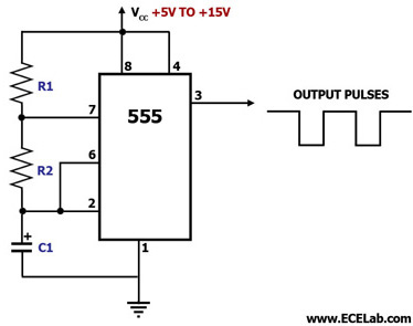
This circuit diagram illustrates the configuration of a 555 timer integrated circuit (IC) as an astable multivibrator. An astable multivibrator is a timing circuit characterized by unstable 'low' and 'high' states. Consequently, the output of an astable multivibrator continuously...
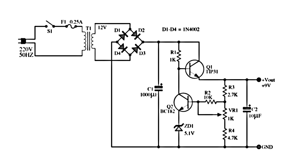
The power supply described utilizes a regulator composed of two NPN transistors. One transistor functions as the power regulator, while the other controls the output voltage. This power supply offers an adjustable output voltage range of 6-12 VDC. The...
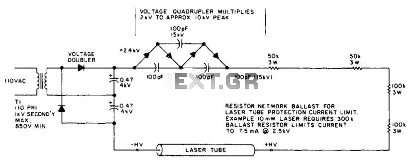
This circuit delivers a peak voltage of 10 kV, while limiting the current to 7.5 mA at 2 kV. The resistors included in the design serve the purpose of ballasting. Additionally, the starting circuit is unable to sustain the...
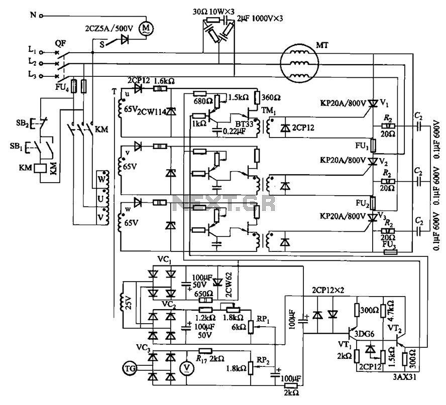
The circuit depicted in Figure 3-181 comprises three thyristors, labeled V1 to V3. The trigger circuit utilizes a single-junction transistor relaxation oscillator. The speed control circuit incorporates negative feedback. A master adjust potentiometer, designated as RPi, is used to...
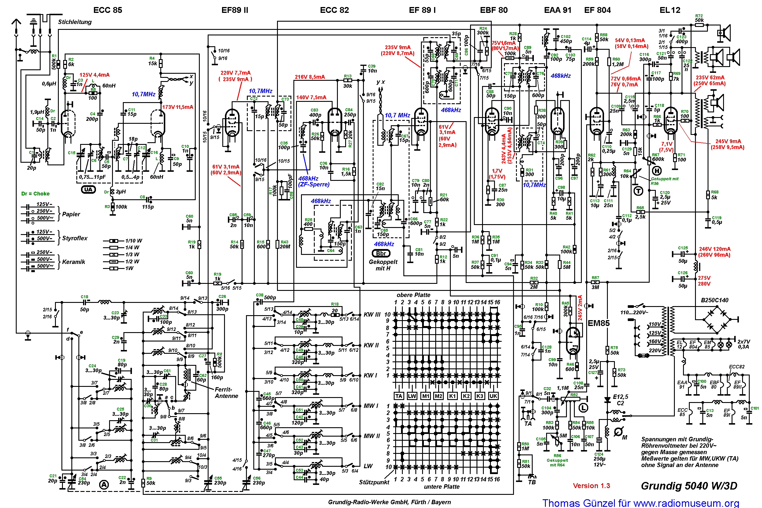
The primary winding of the first IF transformer lacks a capacitor, indicating that it functions as a single tuned circuit with the primary coil serving solely as an inductive coupling. The routing of the twisted pair cannot be replicated...
Warning: include(partials/cookie-banner.php): Failed to open stream: Permission denied in /var/www/html/nextgr/view-circuit.php on line 713
Warning: include(): Failed opening 'partials/cookie-banner.php' for inclusion (include_path='.:/usr/share/php') in /var/www/html/nextgr/view-circuit.php on line 713