
Good FM Transmitter Circuit
The FM transmitter circuit operates effectively by utilizing two key transistors, BF494 and BC548. The BF494 transistor, a high-frequency NPN transistor, is used in the modulation stage to generate a VHF signal. Its configuration allows for efficient modulation of the audio input, which is fed into the base terminal. The audio signal level can be fine-tuned using the variable resistor (VR1), ensuring optimal performance based on the audio source.
Following modulation, the signal is amplified by the BC548 transistor, which is designed for low-power amplification. The inductive coupling between the two stages ensures that the modulated signal is efficiently transferred for amplification, minimizing signal loss. The output of the BC548 transistor drives the antenna matching network, which is critical for maximizing the effective radiated power. The variable capacitor (VC2) in the matching network allows for impedance matching to the antenna, thus enhancing the transmission range, which can reach up to 500 meters under ideal conditions.
The inclusion of capacitors C9 and VC2 helps filter out unwanted frequencies and stabilize the output signal. Housing the transmitter in a metallic cabinet serves to shield it from external electromagnetic interference, which can degrade performance. A regulated DC power supply is recommended to maintain consistent voltage levels, which is crucial for the frequency stability of the transmitter.
For enhanced performance, particularly in terms of range and signal clarity, a telescopic antenna is suggested. This type of antenna can be adjusted for optimal length based on the frequency of operation, thus improving the gain and overall transmission effectiveness. The design of coils L1 and L2, wound on the same air core, ensures that the magnetic coupling between them is maximized, further enhancing the efficiency of the transmitter circuit. Proper winding techniques and spacing between coils are essential to minimize parasitic capacitance and inductance, ensuring a stable and robust FM transmission system.This house FM transmitter for your stereo or any other amplifier provides a good signal strength up to a distance of 500 meters with a power output of about 200 mW. It works off a 9V battery. The audio-frequency modulation stage is built around transistor BF494 (T1), which is wired as a VHF oscillator and modulates the audio signal present at the
base. Using preset VR1, you can adjust the audio signal level. The next stage is built around transistor BC548 (T2), which serves as a Class-A power amplifier. This stage is inductively coupled to the audio-frequency modulation stage. The antenna matching network consists of variable capacitor VC2 and capacitor C9. Adjust VC2 for the maximum transmission of power or signal strength at the receiver. For frequency stability, use a regulated DC power supply and house the transmitter inside a metallic cabinet. For higher antenna gain, use a telescopic antenna in place of the simple wire. Coils L1 and L2 are to be wound over the same air core such that windings for coil L2 start from the end point for coil L1.
Coil winding 🔗 External reference
Related Circuits
The TDA integrated circuit series is highly regarded and widely utilized in amplifier designs and projects. TDA audio amplifier circuits are primarily produced by Philips and SGS-THOMSON. The most commonly used ICs include the TDA2030 and TDA2003 for small...
The LM4844 is an integrated audio subsystem designed for stereo cell phone applications. Operating on a 3.3V supply, it combines a stereo speaker amplifier delivering 495mW per channel into an 8Ω load and a stereo OCL headphone amplifier delivering...
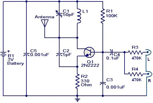
This weblog focuses on electronic circuit schematics, PCB design, DIY kits, and diagrams for electronic projects. The FM transmitter circuit utilizes the NPN transistor 2N2222. The inductor L1 and capacitor C1 generate the necessary oscillations for Q1. The collector...
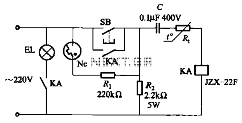
The circuit illustrated in Figure 2-49 is straightforward, featuring a cold Positive Temperature Coefficient (PTC) thermistor element. It utilizes the thermal resistance characteristics of the lamp to manage the delay time, which typically ranges from 10 to 30 seconds....
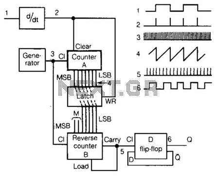
An input rectangular signal is differentiated to produce short impulses from its edges. These impulses transfer the content of counter A to a latch that clears the counter after a very brief period. Counter A counts impulses at a...
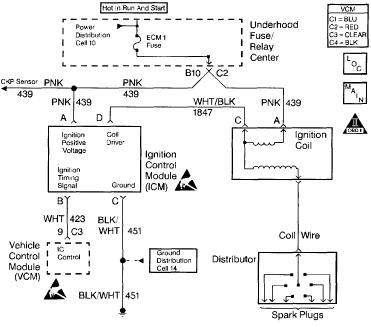
Chevy S-10 Blazer Ignition Control (IC) Circuit Wiring Diagram. The Chevy S-10 Blazer ignition control circuit is a critical component in the vehicle's ignition system, responsible for managing the timing and operation of the engine's spark plugs. The circuit typically...