
Metal Detector Circuits Schematic Diagram

This comprehensive description outlines the operation and components of a beat frequency oscillator (BFO) metal detector circuit, emphasizing the importance of frequency selection, tuning, and the relationship between coil size and detection capabilities. The design considerations highlighted ensure that the metal detector operates effectively across various conditions while maintaining sensitivity and accuracy.One type of metal detector is a type of beat frequency oscillator (BFO). The methods used in metal detectors in general are changing the characteristics of the oscillator when there are close to the metal sensor. The detector works based on the resonant frequency that has been set change when there is a metal object is located quite close to the s
earch coil sensors. Tuning circuit (tuned circuit) should be a part of our oscillator circuit so that if approached by a metal coil sensor specific hence the output frequency of the oscillation circuit is about to change. Variation changes the output frequency depends on the frequency chosen. The selection of the higher frequency will cause the circuit sensitivity increases because the greater the frequency change.
Stay if the selection frequency is too high then the practice will produce a system that is not sensitive. This is because the high frequency of most will not be reflected back but will be absorbed by the soil, building materials.
Frequency used (f1-produced by the tank circuit with L1) is usually above the human hearing ability. Because it can not be heard by human pendegaran the frequency changes that occur will also not be heard as well. To overcome this it should be made a separate tone (audible frekuency-f2) which shows the change in frequency.
This is said with the beat. By mixing the two signals (f1 and f2) will produce signals f1, f2, (f1 + f2), and (f1-f2). The signal can be heard by human hearing is a signal (f1-f2). So when there are changes in frequency caused by changes in the characteristics of the search coil can be heard by humans as a rhythm-beat changing. Rhythm-beat is what is the signal (f1-f2) earlier. VC1 setting is not easy because it requires experiments on certain metals. Similarly, for setting the rhythm of the beat is heard because at a certain condition will feel the rhythm of this beat very disturbing.
So it was no possibility the beat or rhythm is not produced beatnya lower than normal because all these conditions can be set on VC1. So when there are changes in the characteristics of the search coil it will produce sound frequency also depends on the different frequencies generated by the L1 and L2 frequencies generated by.
This method still has the disadvantage that its output frequency variation is still too small to change its frequency is almost not visible. Additionally, on certain conditions Dapa produce a frequency below the audible sound. For that we need a reconfiguration of coupling capacitors and the frequency of use. The values of existing components dirangkaian Figure 2 represents the values specified in a metal. So for a specific metal component values need to be adjusted especially VC1, C1, C4, and C5. Inductor L1 is formed from the coil that serves as a search coil. This inductor will resonate along with the VC1 to produce a tank circuit with Q high. The second oscillator is formed from L2, C4, C5, R4, and Q2 and the oscillator circuit will produce a signal with a fixed frequency.
D1 serves as a simple mixing between f1 and f2 and will generate a signal with a frequency (f1-f2) and a lot of harmonic signals. Signal with a frequency (f1-f2) is made so that it can be in areas that can be heard by human hearing.
Suppose that f1 and f2 on the 100KHz 101KHz then after dimixer, signal (f1-f2) will produce a signal with a frequency of 1kHz. This differential signal must be amplified in advance using a opamp that will only be able to drive headphones with high impedance.
If the chill to be used for regular headphones then Dapa LM741 amplifier chip is replaced with the type of audio amplifiers. Because ampilifier audio output has a low impedance. Amplifier gain setting is determined from the setting R7 and R10, and if necessary the output of the LM741 can be incorporated into a power amplifier circuit to drive an spaker.
Circuit in Figure 2 is very simple to allow the occurrence of frequency drift - a shift in frequency. This is usually caused by the temperature factor. However this problem is not a serious problem. Permsalahan can ditanganni by searching for capacitor components which have a large enough temperature tolerance.
In addition, PCB layout also has a huge effect on this problem. The size of the search coil depends on the sensitivity of metal detectors are cooled and form of the sensor itself. For example, a large search coil which of course can easily find the metal you are looking at a large area rather than a metal detector with a small search coil.
Instead of metal detectors can not determine the location of cables on a wall tertanan precisely because of the large size of the sensor. So the greater the search coil, the accuracy of his smaller but bigger sensitivty but instead a small search coil, commonly used to compact metal detector, have high accuracy but less sensitivity.
The shape of the search coil is usually a circle or square. Besides needing a shield layer which serves to reduce electrostatic effects and effects caused by capacitive objects. You are reading the Circuits of Metal Detector Circuits And this circuit permalink url it is 🔗 External reference
Related Circuits
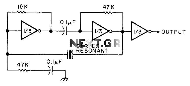
The circuit diagram illustrates the connection of all three components of the series resonant crystal and triple CD4049 inverter. The supply voltage range is between 3 to 15 volts, making it suitable for various applications. This design is compact...
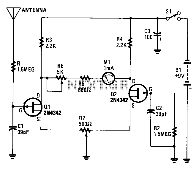
The core of the electroscope consists of two junction FETs, Q1 and Q2, arranged in a balanced-bridge circuit. The gate input of Q1 is connected to a wire pick-up antenna, while the gate of Q2 is connected to the...
A small bias on the bases of Q1 and Q2 through R1 and R2 assists in initiating the circuit. This provides each transistor's base with a slight forward bias, enabling both transistors to conduct when the circuit is initially...
AC power is rectified and applied to the motor in one polarity when the momentary switch is held in one direction, and the polarity is reversed when the motor is held in the reverse direction. The remote car starter...
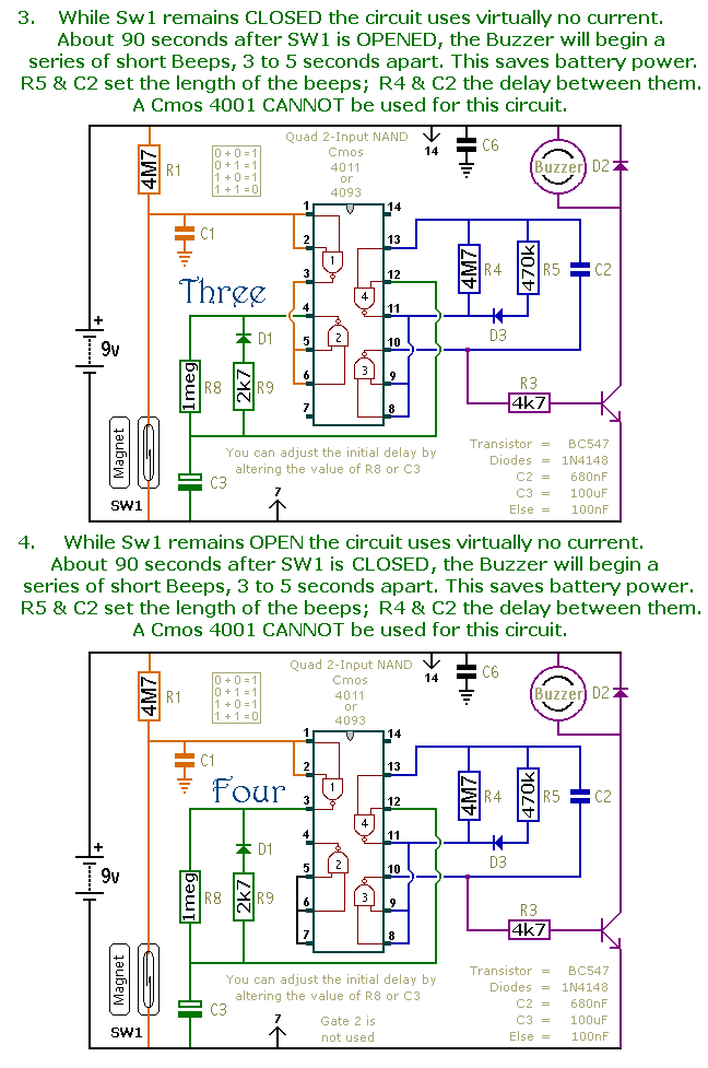
This is a collection of compact, self-sufficient alarm circuits designed for low standby current, making them ideal for battery operation. Some circuits are activated by normally-open and normally-closed switches, while others respond to variations in light or temperature. This...
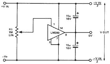
A simple split power supply circuit can be designed using the schematic diagram based on the LM380 audio power integrated circuit (IC). The output voltage regulation is dependent on the circuit feeding the LM380. The power dissipation is approximately...