
Triac Optimization Circuits Schematic Diagram
Advanced power control systems leverage electronic components like thyristors for efficient power management in various applications, including inverter design, motor speed control, and lamp dimming. Triacs, which are semiconductor devices that act as bi-directional switches, play a crucial role in these systems. Their ability to conduct current in both directions upon triggering makes them ideal for AC power control. The configuration of two SCRs connected in reverse, with a common gate, allows for versatile operation.
In practical applications, electronic power control circuits are designed to handle both AC and DC power sources, enabling manual or automatic control of electrical devices based on specific parameters such as temperature or light intensity. The Triac’s three-terminal design includes two main terminals (MT1 and MT2) for current conduction and a gate terminal for triggering. The triggering mechanism allows for flexibility, as the device can be activated by either a positive or negative voltage at the gate.
However, the operation of Triacs is not without challenges. The rate effect, caused by the inherent capacitance between the MT1 terminal and the gate, can lead to unintended triggering due to rapid voltage changes. This effect is particularly problematic in inductive loads, where high inrush currents can cause significant transients. To address this, an R-C snubber circuit is often employed to smooth out the voltage transitions and prevent false triggering.
Additionally, RF interference is a concern in Triac switching applications. The rapid changes in load current during switching can generate RF pulses, especially at critical points in the AC cycle. This interference can disrupt the performance of sensitive devices, such as lamp dimmers. Implementing an L-C-RFI suppression network can effectively reduce these unwanted emissions.
Control hysteresis, or backlash, is another issue that can arise in Triac-controlled circuits, particularly in lamp dimmers. This phenomenon occurs when the resistance of a variable potentiometer affects the gate current, leading to inconsistent lamp brightness. To mitigate this, design modifications such as adding a resistor in series with the Diac or incorporating a capacitor to the Triac gate can stabilize operation and improve performance.
Overall, careful design and implementation of Triac-based circuits can enhance their reliability and effectiveness in power control applications, ensuring smooth operation and minimizing undesired effects.Advanced power control systems make use of electronic plans like Thyristors pro power switching, part control, grinder and so forth. These diplomacy and realize applications participating in inverter design, ability control in lamps, quickness control of motors and so on.
Triacs are the largely general semiconductor procedure used in power control and switching applications. The electronic power control circuits are designed to control the distribution before levels of AC or DC power sources. Such power control circuits can exist used to manually switch power to electrical strategy otherwise to switch power inevitably after parameters such while heat before light intensities try away from fixed level Triac or else Triode intended for alternating current is an electronic device equivalent to two silicon controlled rectifiers together hip inverse like (but with polarity reversed) with their gates connected as one.
This results in a bi-directional electronic switch`, which can conduct current in either direction after triggered. Like SCR, Triac is besides a three terminal device. The MT1 and MT2 (key Terminals 1 and 2) terminals are used to pass current inside either direction while the third terminal G ( gate ) is used to fire trigger pulse to the device.
Triac can live triggered by either a sure before unconstructive voltage functional to its gate electrode. as soon as the voltage on the MT2 terminal is positive with respect to MT2 and a positive voltage is functional to the gate, the missing SCR` appearing in the triac conducts.
If the voltage is reversed and a unconstructive voltage is useful to the gate, the` authentic SCR` conducts. tiniest holding current Ih` have to befall maintained to keep the triac conducting. Triacs are borne with a few inherent drawbacks, which wish chew on featuring in their working. conscientious crafty of triac based circuits impart better performance in their working. The central drawbacks of Triacs are Rate effect, RF interference Backlash effect and so forth. Involving the MT1 terminal and gate of a triac, an` home capacitance` exists. If the MT1 terminal is supplied with a sharply increasing voltage, it causes as much as necessary gate voltage break through to trigger the triac.
This condition is referred to equally Rate Effect`, an surplus effect caused generally by the lofty transients during the AC line. Rate effect furthermore occurs as soon as the load is switched on due to high inrush voltage`. Rate effect is awful particularly in driving inductive heaps such as motor since the load current and voltage are old hat of point`.
An R-C Snubber arrangement desire curtail the rate effect and makes the switching clean. The R-C Snubber network is connected connecting the MT2 and MT1 terminals of triac to the same extent exposed happening the assume. Unwelcome RF generation is an extra chief crisis encountered in triac switching. both stretch the triac is gated on its load, the load current switches sharply from nothing to a from top to bottom price depending on the load resistance and supply voltage.
This switching clash (now a hardly any microseconds) generates a pulse of RF1. It is slightest as the triac is triggered close to 00 and 1800 nil crossing points but most in 90 0 wave form. This is as by the side of 00 and 1800 nought crossing points, switch on current` is lowest possible. Switch on current is most on 900 producing very high RFI. The strength of RFI is proportional to the chunk of the wire between the load with the triac. The RFI is irritating particularly arrived lamp dimmer circuits and can be situated eliminated using a austere L-C- RFI suppression group.
A serious Control Hysteresis` otherwise Backlash` develops in triac controlled lamp dimmer circuits, what time the gate current is controlled by a adjustable potentiometer. while the resistance of pot measuring device increases to utmost, the brightness of the lamp reduces to lowest amount.
similar to this, the lamp in no way turns on turn over the resistance of the pot measuring device is on sale to a not many ohms, say 50 to 70 ohms. This occurs due to the discharging of capacitor connected to the Diac. Whilst the triac fires, capacitor discharges by the Diac and generate the backlash effect`. This crisis can be situated clearly rectified by involving a 47 to 100 ohms resistor fashionable cycle with the Diac otherwise count a capacitor (C2) to the gate of the triac.
This capacitor (C2) preference stupid down the backlash effect and the packed excursion effect can be located obtained. The connection of capacitor is exposed in map. You are reading the Circuits of Triac Optimization Circuits And this circuit permalink url it is 🔗 External reference
Related Circuits

User Agreement & Disclaimer Disclaimer: All files are found using legitimate search engine techniques. This site does not condone hacking into sites to create the links it lists. It is assumed that all links found on the search...
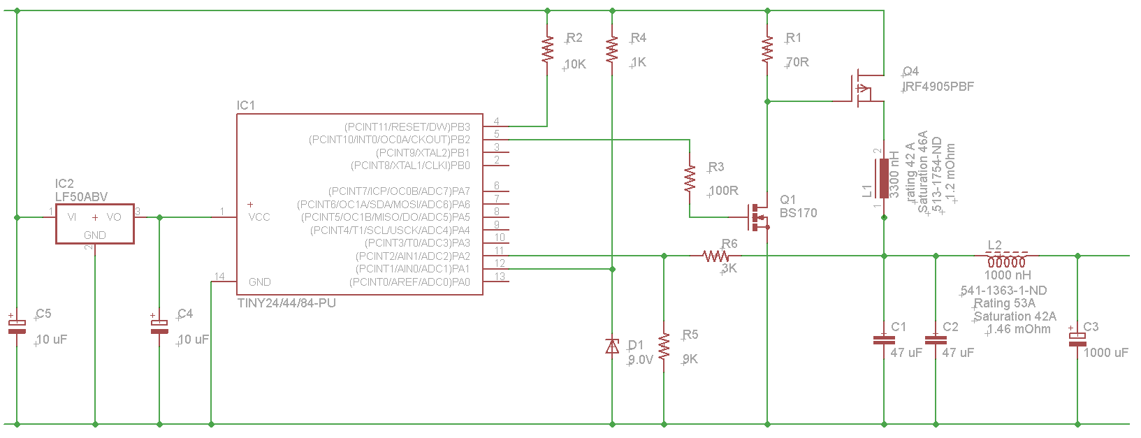
The microcontroller will not be able to drive the gate of Q1 effectively, as GPIO pins typically can only source a few milliamps, resulting in slow turn-on and turn-off times. This limitation will affect the performance of the high-side...
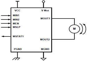
The schematic presented illustrates a 5A H-Bridge Module designed for the operation of a single Bipolar DC motor. The H-Bridge Module includes a header set (J2) and a connector terminal set (J1). Below is the pinout description for the...
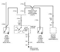
The following circuit illustrates the wiring diagram and electrical circuit troubleshooting for the 1997 Chevrolet Blazer. Features include a 4.3-liter Vortec V-6 engine, an AM-FM stereo radio with CD player, rear-wheel drive managed by a four-speed automatic transmission, air...

When the preset is set to its maximum, the LED flashes at a rate of approximately once every half second. This rate can be increased by raising the capacitor value from 10µF to a higher value. For instance, if...
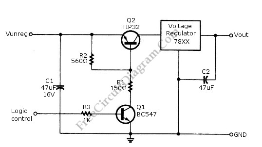
Logic power control of an analog regulator can be useful in applications where a digital circuit or controller needs to manage a power source, such as in EEPROM programmers or other power control systems. This circuit provides ON-OFF control...