
YUV/YCbCr to RGB converter

The device's component video output is designed to provide high-quality video signals by separating the video information into multiple components. This method enhances the image quality compared to composite video signals, as it reduces interference and allows for higher resolution displays. The component video output typically consists of three separate signals: Y (luminance), Pb (blue minus luminance), and Pr (red minus luminance). This separation enables better color accuracy and detail in the video output.
It is important to note that while the component video signal shares similarities with RGB signals, they are fundamentally different in terms of signal structure and compatibility. RGB signals transmit color information through three separate channels (red, green, and blue), whereas component video uses a different encoding method. As a result, component video outputs cannot be directly connected to RGB monitors, which are designed to interpret RGB signals.
For optimal performance, the device should be connected to a compatible display that supports component video inputs. This setup will ensure that the full potential of the video quality is realized, providing an enhanced viewing experience for video playback and gaming. Users should refer to the specifications of their display devices to confirm compatibility with component video signals.Video recorder, DVD player and TV game, have component video output. The component video signal is like RGB video signal, but it cannot connect to RGB monitor. 🔗 External reference
Related Circuits
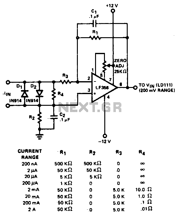
The converter features eight decades of current range. The circuit is intended to be used with the 200 mV range of a DVM. The described converter circuit is designed to accommodate a wide range of current measurements, spanning eight decades....
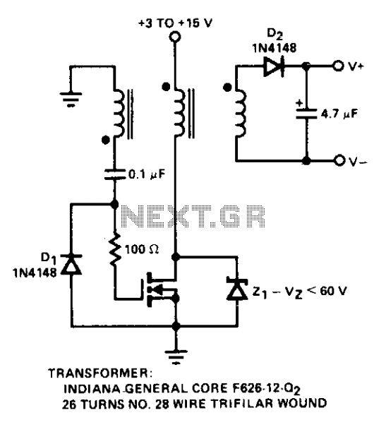
Diode D1 prevents negative spikes from occurring at the MOSFET gate. The 100-ohm resistor acts as a parasitic suppressor, while Z1 functions as a dissipative voltage regulator for the output and clips the drain voltage to a level below...
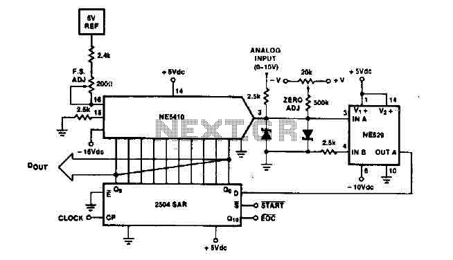
The time IO-bit conversion operates at 3.3 MHz with a clock signal. This converter utilizes a 2504 12-bit register in successive approximation mode, where the conversion signal for the short-cycle end is derived from the first bit utilized in...
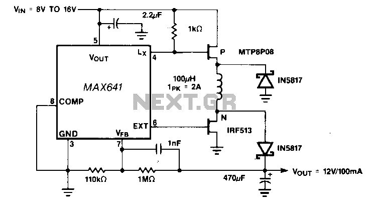
Positive output step-up and step-down converters have a common limitation in that neither can handle input voltages that are both greater than or less than the output. For example, when converting a 12-V sealed lead-acid battery to a regulated...
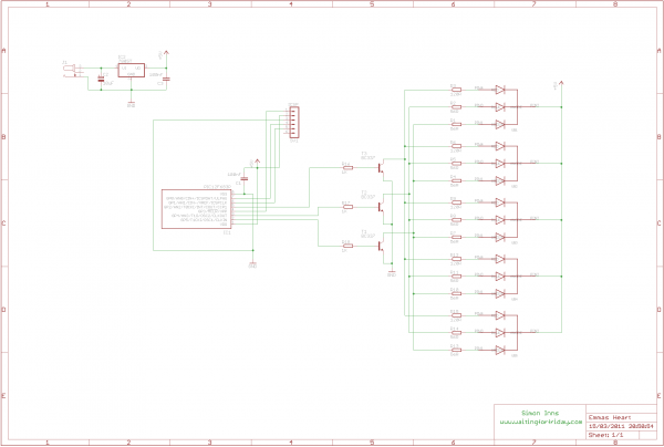
This project involves creating an RGB LED-lit love heart controlled by a PIC12F683 microcontroller. The design serves as a gift for a 15th wedding anniversary. The heart is crafted from a 200x150x6mm sheet of plexiglass, which is cut and...
A standard serial interfacing for PC, RS232C, requires negative logic, i.e., logic 1 is -3V to -12V and logic 0 is +3V to +12V. To convert a TTL logic, say, TxD and RxD pins of the uC chips, thus...