
RS232C Level Converter

The RS232C standard is widely employed for serial communication between computers and peripheral devices, utilizing negative logic levels where a logic '1' is represented by a voltage range of -3V to -12V and a logic '0' by a voltage range of +3V to +12V. This requires a level shifting mechanism when interfacing with microcontrollers (uCs) that typically operate at TTL levels (0V to +5V).
The MAX232 chip serves as a common solution for this purpose, facilitating the conversion between TTL and RS232 levels. It features two channels, allowing for simultaneous transmission and reception of data (TxD and RxD). The MAX232 requires four external 10µF capacitors to function correctly, which are used for the internal charge pump circuitry that generates the necessary negative voltage levels. It is crucial to ensure the correct polarity of these capacitors during assembly to avoid damage to the chip and ensure proper operation.
In contrast, the DS275 offers a more compact solution, eliminating the need for external capacitors, thus simplifying the design and reducing the board space required. The DS275 integrates the charge pump internally, allowing for a more straightforward implementation while maintaining compatibility with RS232 standards. This makes it particularly suitable for applications where space is at a premium or where ease of assembly is a priority.
When designing a circuit for RS232 interfacing using either the MAX232 or DS275, attention must be paid to the layout to minimize noise and ensure signal integrity. Proper grounding and decoupling techniques should be employed to enhance performance, especially in high-speed communication scenarios. The selection between these two options will depend on specific application requirements, including space constraints, component availability, and overall system complexity.A standard serial interfacing for PC, RS232C, requires negative logic, i.e., logic `1` is -3V to -12V and logic `0` is +3V to +12V. To convert a TTL logic, say, TxD and RxD pins of the uC chips, thus need a converter chip. A MAX232 chip has long been using in many uC boards. It provides 2-channel RS232C port and requires external 10uF capacitors. Carefully check the polarity of capacitor when soldering the board. A DS275, however, no need external capacitor and smaller. 🔗 External reference
Related Circuits
This audio meter can be monitored using a small panel meter with a circuit constructed from discrete components. The audio level meter circuit exhibits a flat frequency response ranging from approximately 20Hz to over 50kHz. The input sensitivity is...
To achieve optimal performance as a low noise, high input impedance device, the preamplifier and tone control utilize JFET technology. The circuit is designed to minimize harmonic distortion levels. The use of Junction Field Effect Transistors (JFETs) in the preamplifier...
When the power supply is connected to IC1, the output pin 3 operates at a frequency of 1 kHz. The components Q1 and Q2 work in a push-pull configuration. When a positive output signal is generated, Q1 and Q2...
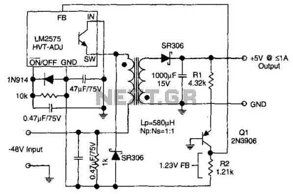
The circuit supplies 1 A at +5 V from the -48 V supply commonly used in telephone equipment. More: The National Semiconductor LM2575 is a simple switching regulator. The circuit utilizes the National Semiconductor LM2575, which is a step-down (buck)...
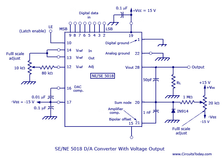
Monolithic and hybrid digital-to-analog converters utilizing MC 1408 IC and SE/NE 5018, including specifications and applications. Digital-to-analog converters (DACs) are integral components in various electronic systems, enabling the conversion of digital signals into corresponding analog voltages or currents. The MC...
This sound level meter serves as an effective one-chip replacement for standard analog meters. It is entirely solid-state, ensuring durability and longevity. The circuit is built around the LM3915 audio level integrated circuit (IC) and requires only a minimal...