
YUV(YCbCr) to RGB converter
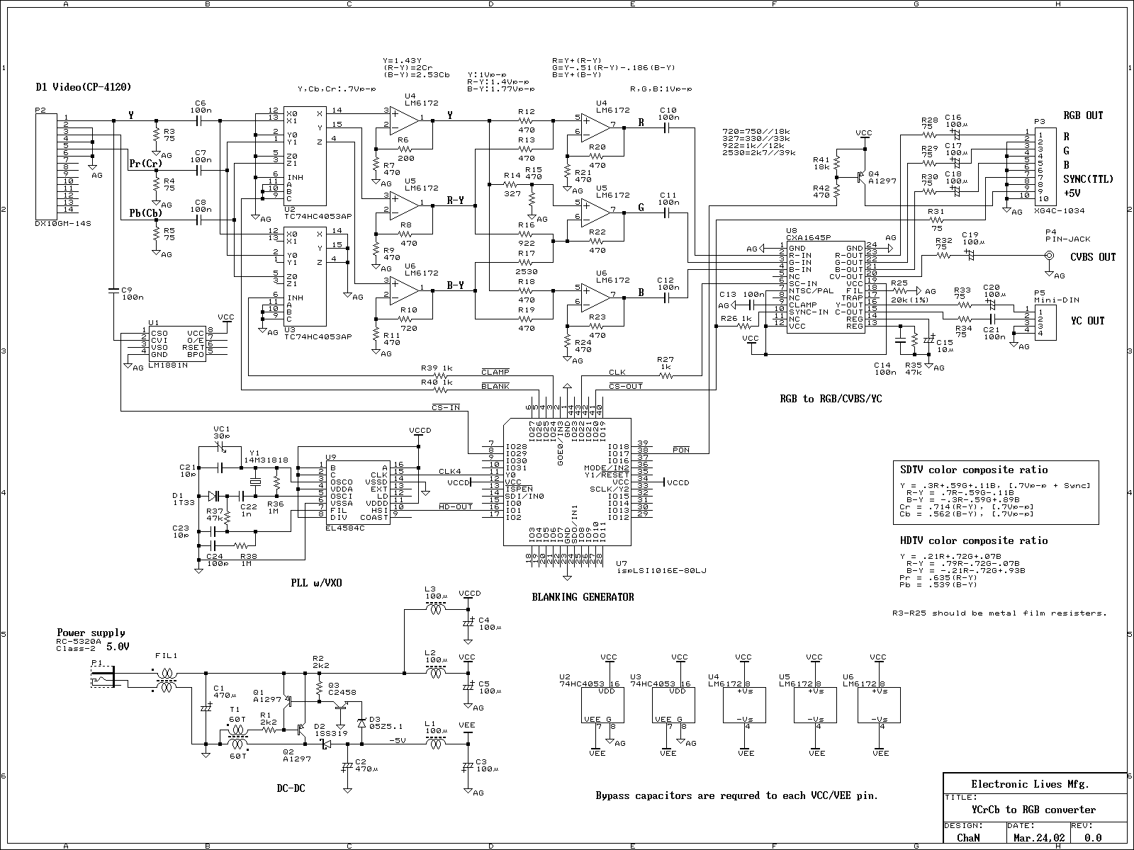
The YUV to RGB converter is an essential circuit for interfacing modern video equipment with legacy displays that lack direct component video input. This converter takes the YUV (or YCrCb) format, which separates luminance (Y) from chrominance (U and V) information, and transforms it into the RGB format used by older monitors and televisions.
The typical architecture of a YUV to RGB converter includes several key components. First, an analog front end is employed to receive the YUV signals. This front end may consist of operational amplifiers configured to buffer and scale the incoming signals to appropriate levels for further processing.
The core of the conversion process is achieved through a series of matrix multipliers. The YUV signals are mathematically transformed into RGB using the following equations:
- R = Y + 1.402 * (V - 128)
- G = Y - 0.344136 * (U - 128) - 0.714136 * (V - 128)
- B = Y + 1.772 * (U - 128)
These equations indicate that the Y component contributes directly to the RGB outputs, while the U and V components are used to adjust the color information. The constant values in the equations are derived from the standard conversion coefficients for the YUV color space.
After the conversion, the RGB signals may require further conditioning to match the voltage levels and impedance characteristics of the target display. This may involve additional amplification stages or filtering to minimize noise and ensure signal integrity.
Finally, the output stage of the converter is designed to drive the RGB inputs of the display device. This can include buffering circuits to prevent loading effects that may degrade the video quality. In some designs, additional features such as sync signal generation may be incorporated to ensure proper timing and synchronization with the display.
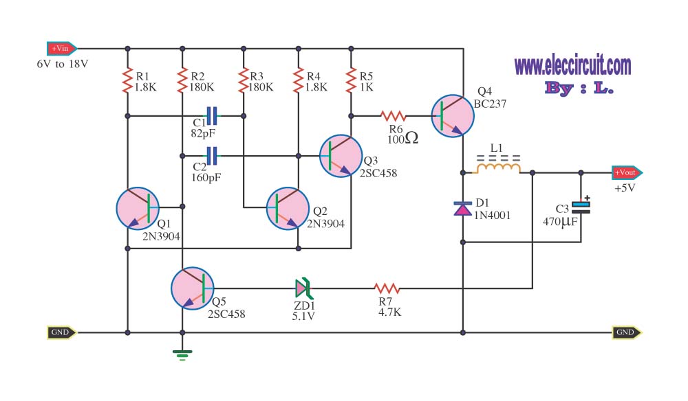
Overall, the YUV to RGB converter is a critical component in bridging the gap between modern digital video sources and older analog display technologies, enabling the continued use of legacy equipment in contemporary video applications.Recently, most digital video equipments, such as video recorder, DVD player and TV game, have component video output. The component video signal is like RGB video signal, but it cannot connect to RGB monitor directly. Thus I designed and built YUV(YCrCb) to RGB converter to use old TV monitor or video equipment which does not have component video input.
🔗 External reference
Related Circuits
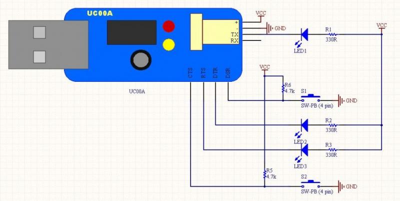
The LEDs operate in an active-low configuration (0), while the initial state of the switches is high (1). In other words, the PC software must send a low signal (0) to activate the LEDs, and if a low signal...
A tachometer can be constructed using the TC9400 in frequency-to-voltage (F/V) mode to convert frequency information (RPM) into a linearly proportional voltage. This voltage can then be compared to one of several comparators (in this example, using eight). The...
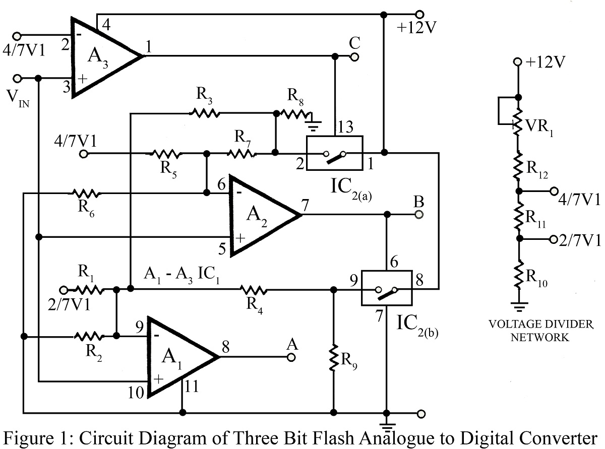
The flash type converter is the simplest and fastest type of analog-to-digital converter. The entire digital output word is available immediately after the propagation delay time of the comparators and the encoding logic gates. A typical conversion time for...
The circuit reduces voltage size or functions as a step-down voltage converter circuit, which is a DC regulated circuit model utilizing a switching converter. This design generates a specific voltage output. The step-down voltage converter, also known as a buck...
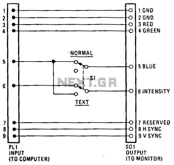
The RGB blue box allows users to change their PC's RGB monitor screen to a blue background at the flip of a switch. It enables the display of bright white text on a blue background instead of the typical...
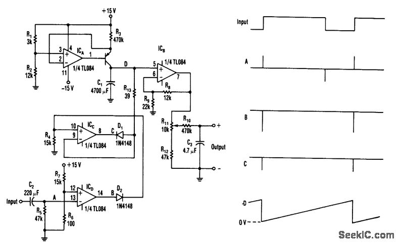
When the input transitions from low to high, a narrow positive pulse is generated at point A. This pulse results in a -13 V level at point B, which causes diode D2 to turn off. Consequently, the V+ voltage...
Warning: include(partials/cookie-banner.php): Failed to open stream: Permission denied in /var/www/html/nextgr/view-circuit.php on line 713
Warning: include(): Failed opening 'partials/cookie-banner.php' for inclusion (include_path='.:/usr/share/php') in /var/www/html/nextgr/view-circuit.php on line 713