
USB to serial converter circuit

Whenever the state of these input pins changes, the program under the handler function will execute. After connecting the UC00A with the additional circuit, the software can be run for testing. Upon connection, LED2 and LED3 will blink several times, indicating the establishment of the serial connection. The graphical user interface (GUI) will display the virtual COM port created by the UC00A, typically shown as COM22, which is the highest number unless multiple UC00A devices are connected simultaneously. After selecting the appropriate COM port, clicking "Connect" will establish serial communication between the PC and the UC00A. The correct sequence of operations is that when switch S1 (DSR) is pressed, LED2 (DTR) lights up, and when switch S2 (CTS) is pressed, LED3 (RTS) lights up. Once the functionality of the circuit and program is confirmed, the system volume can be adjusted by adding functions that increase and decrease the volume through switch presses.
The described circuit employs a microcontroller to monitor the state of the DSR and CTS pins, facilitating communication between the PC and the UC00A module. The active-low configuration of the LEDs ensures that they illuminate when the corresponding control signal is low. The integration of the "PinChanged" event allows for real-time monitoring of the input states, enabling immediate feedback on user interactions. This is particularly useful for applications requiring prompt response to switch activation.
In the schematic, the UC00A module is connected to the PC via a serial interface, with the DSR and CTS pins routed to the microcontroller's input pins. The LEDs are connected to the output pins of the microcontroller, with appropriate current-limiting resistors in series to prevent damage to the LEDs. The switches S1 and S2 are connected to ground, ensuring that when pressed, they pull the respective input pins low. The software running on the PC is designed to handle the serial communication, reading the status of the DSR and CTS pins and updating the LED states accordingly.
Additionally, the implementation of volume control through the switches enhances the functionality of the circuit. By assigning specific functions to the switches, users can conveniently adjust the system volume, making the design more versatile. The overall design emphasizes the importance of user interface responsiveness and provides a practical application of serial communication in embedded systems.The LEDs are active-low (0) while the switches initial state is high (1). In other word, the PC software needs to give low (0) to on the LEDs and if a low (0) is read from the input pins, corresponding switch is pressed. I’m using the prototyping area provided beside the common 2510 connector on UC00A module . The completed circuit: Now lets continue with the coding. The PC software we need is one which can read the status of the DSR and CTS pins and light up LEDs for indication.
“PinChanged” event is the solution for monitoring of the input pins continuously. It’s similar to microchip PIC’s interrupt-on-change feature.
So whenever the state of those input pins change, it’ll runs the program under the handler function. After plugging in the UC00A with additional circuit, we can run the software and test it! You will notice that LED2 and LED3 blink for several times upon plugin. It’s because of the establishing of serial connection. This is how my GUI looks like after it’s connected to UC00A: COM22 shows the virtual COM port created by UC00A.
Usually it’s the one with greatest number unless you have more than one UC00A connected to your PC at once. After selected the COM port, click on “Connect” will establish the serial communication between your PC and UC00A.
The correct sequence would be when S1 (DSR) is pressed, LED2 (DTR) lights up, and when i press S2 (CTS), LED3 (RTS) lights up. After confirmed the functionality of the circuit and program, since we have two input, we can add the function to increase and decrease the system volume.
So by pressing the switches, the volume of your system can be altered.
Related Circuits
A 555 timer can be used to generate a square wave to produce a negative voltage relative to the negative battery terminal. When the timer output at pin 3 goes positive, the series 22 uF capacitor charges through the...

A circuit utilizing a single analog multiplier and five precision resistors can produce an output voltage (Ko) that represents a second-order polynomial. This circuit implements the quadratic function. The input terminals of IC1 are configured to create a positive...
These small electronic lamps are quite practical and have a long lifespan. Approximately 40 years after Nick Holonyak invented the first LED, they have become nearly essential. Any dedicated electronics enthusiast typically keeps a few in their collection. Prior...
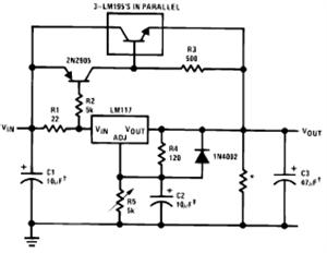
The LM117/LM317 from National Semiconductor Corporation is a three-terminal adjustable positive voltage regulator integrated circuit (IC). The output voltage range of the LM117/LM317 is from 1.2V to 37V with a load current capability of up to 1.5A. It is...

The adjustment potentiometer for the Raspberry Pi can modify the conduction angle of the thyristor VI and V2, which in turn adjusts the speed of the DC motor M. The speed feedback circuit is implemented using a tachometer generator...
This circuit is designed for an electrically operated rolling shutter, typically featuring a standard control panel with a three-position switch: up, down, and stop. To automate the opening and closing with a time-controlled switch, additional wiring connections are required....