
z80 cpu test circuit
The Z80 microprocessor, a classic in the realm of computing, requires careful consideration when designing circuits around it. The arrangement of power and ground pins is critical for ensuring stable operation, and while the schematic may deviate from the physical layout of the DIP package, it is essential to maintain clarity in the design. The use of 470-ohm resistors to ground the data lines is a common technique to prevent floating states, ensuring that the microprocessor interprets a defined instruction (NOP) during initialization or when no operation is intended.
Memory mapping is a crucial aspect of system design, particularly when dealing with limited resources. The use of the A15 pin as a selector for RAM and ROM allows for efficient memory management, enabling the system to switch between program storage and data storage seamlessly. This approach not only simplifies the design but also maximizes the utility of available memory, which is vital for small-scale applications.
Interfacing with peripherals such as LCD displays or other I/O devices is another important consideration. The choice of a serial interface for initial display requirements is practical, as it reduces the complexity of the circuit and minimizes the demands on memory. The ability to program service calls for various devices enhances the functionality of the system, allowing for a broader range of applications.
Future expansions, such as additional memory paging or interfacing with more complex devices, will require careful planning and may introduce additional components into the design. While the limitations of the Z80 and similar microprocessors may restrict the complexity of projects, the learning experience gained through such endeavors is invaluable. The historical context of the Z80, including its use in early personal computers like the TRS80, highlights its significance in the evolution of computing technology.
Ultimately, while the Z80 may not compete with modern microcontrollers in terms of functionality and ease of use, it serves as an excellent educational tool for understanding fundamental computing principles and hardware design. Transitioning to microcontroller platforms, such as those in the PIC family, may provide a more straightforward path for experimentation and project development, given their integrated features and lower complexity.GND and VCC are perpendicular to the rest of the pins in the circuit diagrams, whereas the real Z80 is a DIP with no pins at all in these locations. I find that this makes the circuit diagram harder to read. I have to map between the real physical pins and the pins in the diagram. In regard to your second question. When we draw symbols for processors on schematics we often rearrange the pins to make the schematic easy to draw and read. You will soon get used to it. Those 470 ohm resistors place a hex 0x00 on the data lines so that the uP always executes a `NOP` instruction. They arent needed if you later connect an EPROM to the data and address lines, which you will have to do at some point.
A good memory mapping technique for a small computer (very small) like this is to use A15 for the RAM/ROM select bit. When A15 is low (a `0`) it selects ROM, and when high (a `1`) it selects RAM. This maps into 32k of ROM and 32k of RAM but you can use less of each and still use that bit. Once you get some code running in ROM you`ll be able to program service calls for various devices like keypads and LEDs and whatever else you want to drive with it like relays, etc.
You might find it easiest to interface with a Serial type LCD display rather than an actual monitor at first, as any display type you use should have it`s own storage because the on board storage will be so small. You can also map more memory in as pages but that requires more hardware. In the end you probably wont be able to use this for too much other than small stuff. You can build a small word processor or spreadsheet or whatever but it wont be as good as stuff on the modern PC.
You`ll probably end up putting it aside at some point but if all you want is some learning experience then it may not be a total loss. After all, the odds of building a modern system from the ground up designing your own motherboard are pretty much very slim because of the complexity of the modern computer.
If you are uncomfortable with the drawing shown, make a new drawing yourself. Put the pins all in a row the way you want to see them and then trace out what each pin has to connect to and draw it. As long as the right pin numbers connect to the required places you`re ok. Back in the 1980`s Tandy used the Z80 in their computer, called the TRS80. You can look it up on the web. It had two 5. 25 inch floppy drives and a green monitor (green lettering only). You could get a hard drive for it for about 400 dollars and it stored 40 Megabytes of data (yes that is Megabytes not Gigabytes).
In the long run it is probably better to spend the experimenting time working with one of the microcontroller families like the PIC Flash type. You can do a lot with them these days and then you can use them for hardware projects once you become familiar with them.
In the long run it is probably better to spend the experimenting time working with one of the microcontroller families like the PIC Flash type. You can do a lot with them these days and then you can use them for hardware projects once you become familiar with them.
I agree 100%. A good micorcontroller on on a breadboard is where I would start. It takes something like a 4"x6" board with the Z80, RAM, ROM, counters, and IO chips just to get what is now onboard a modern $2 micro controller. Tho 🔗 External reference
Related Circuits
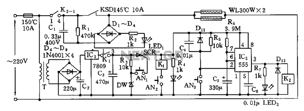
The disinfection cabinet circuit operates on the principle of using infrared heating within a closed cabinet to create a high-temperature environment for disinfecting tableware. The circuit includes an AC buck regulator, an infrared heating circuit, and a timing control...
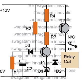
The post discusses a simple delay ON circuit that enables a connected load at the output to be activated with a predetermined delay after the power switch is turned ON. This circuit can be utilized in various applications that...
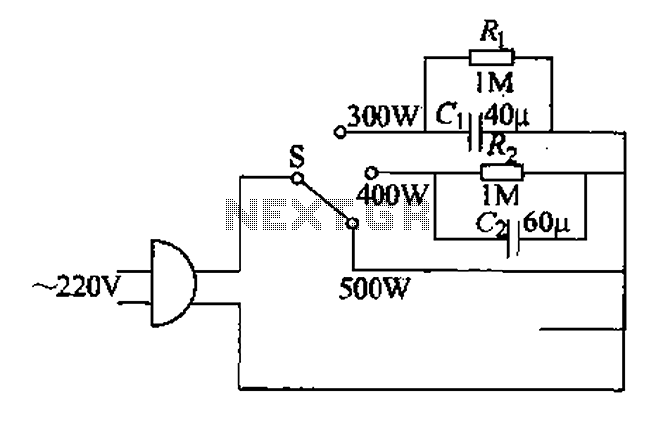
Each family has essential small appliances. The sub-type is an electric power jet, mainly used for clothes and hot shaping. The iron's circuit is shown in Figure 1-30. When using an iron, there is always a concern about using...
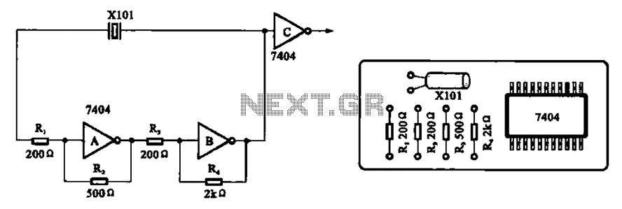
A clock oscillator is commonly utilized in digital signal processing circuits and microprocessor circuits. Digital signal transmission and signal processors necessitate a clock, which serves as the system's timing signal, while the data signal functions as a synchronization signal....
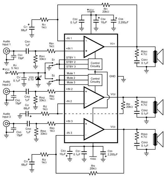
The LM4782 utilizes a protection system known as National Self Peak Instantaneous Temperature (Ke) (SPiKeTM). SPiKe safeguards the output of the LM4782 against over-voltage on the load, short circuits to ground, and provides temperature protection by monitoring instantaneous temperature....
This circuit utilizes the widely available LM3914 integrated circuit (IC). The LM3914 is straightforward to operate, does not require external voltage regulators due to its built-in voltage regulation, and can be powered from nearly any voltage source. This makes...