
Disinfection cabinet electronic control circuit diagram
The disinfection cabinet circuit is designed to ensure effective sterilization of tableware by leveraging infrared heating technology. The primary component, the AC buck regulator, reduces the input AC voltage to a manageable level suitable for the subsequent stages of the circuit. The temperature limit fuse (FU) serves as a safety mechanism, preventing overheating by disconnecting the circuit if the temperature exceeds 150 degrees Celsius.
The transformer (T) steps down the voltage further, allowing the circuit to operate safely at 9V DC. The relay (K1) plays a crucial role in controlling the power to the infrared heating elements by utilizing a single SCR, which acts as a switch that can be triggered to allow current flow when necessary. The SCR is triggered by the power control key (AN1), which must be pressed to initiate the disinfection process.
The infrared heating is activated by pressing the start button (AN3). This action sends a low-level trigger to pin 2 of the 555 timer IC, which is configured in a monostable mode. The timing components, including R5, R6, C4, and C5, define the duration of the output signal generated by the 555 timer. The transient stability time of approximately 24 minutes is critical, as it determines how long the heating elements will operate at high output, ensuring sufficient time for effective disinfection.
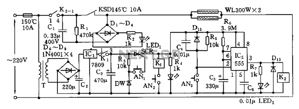
Overall, the circuit is engineered to provide a reliable and efficient method for disinfecting tableware, with built-in safety features and precise timing controls to enhance user experience and operational safety.Disinfection cabinet circuit principle is the use of infrared heating, in a closed cabinet to create a high-temperature environment, tableware disinfection. Circuit shown in FI G. The control circuit includes an AC buck regulator circuit, infrared heating circuit and the timing control circuit. Single-phase AC power by the temperature limit fuse FU (10A, 150 degrees C) was added to the primary of the transformer T, through the buck, rectifier, regulator, the output voltage of 9V DC, the K1 normally closed contact (1-3) to a single SCR SCR anode to.
AN1 is the power control key, pressing, SCR trigger turn-on, power-on control. AN3 is infrared heating start button, press it, a low level of 2 feet 555 555 trigger set .555 and R5, R6, C4, C5 and other components single stabilizing circuit, when it temporarily stable td 1.1R6C5. FIG. the parameters shown transient stability time of 24 minutes, the duration of 3 feet high output is 555 about 24 minutes.
Related Circuits
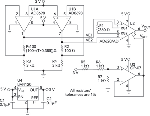
Bridge circuits are widely used for conditioning signals from resistive sensors. These circuits are sensitive to minor changes in resistance, providing a differential output from a single current or voltage source. However, the sensors connected to a passive bridge...
The program utilizes the internal 4 MHz oscillator of the PIC16F628 microcontroller in a two-input alarm circuit. The two-input alarm circuit designed with the PIC16F628 microcontroller leverages the internal 4 MHz oscillator to provide a stable clock signal for operation....
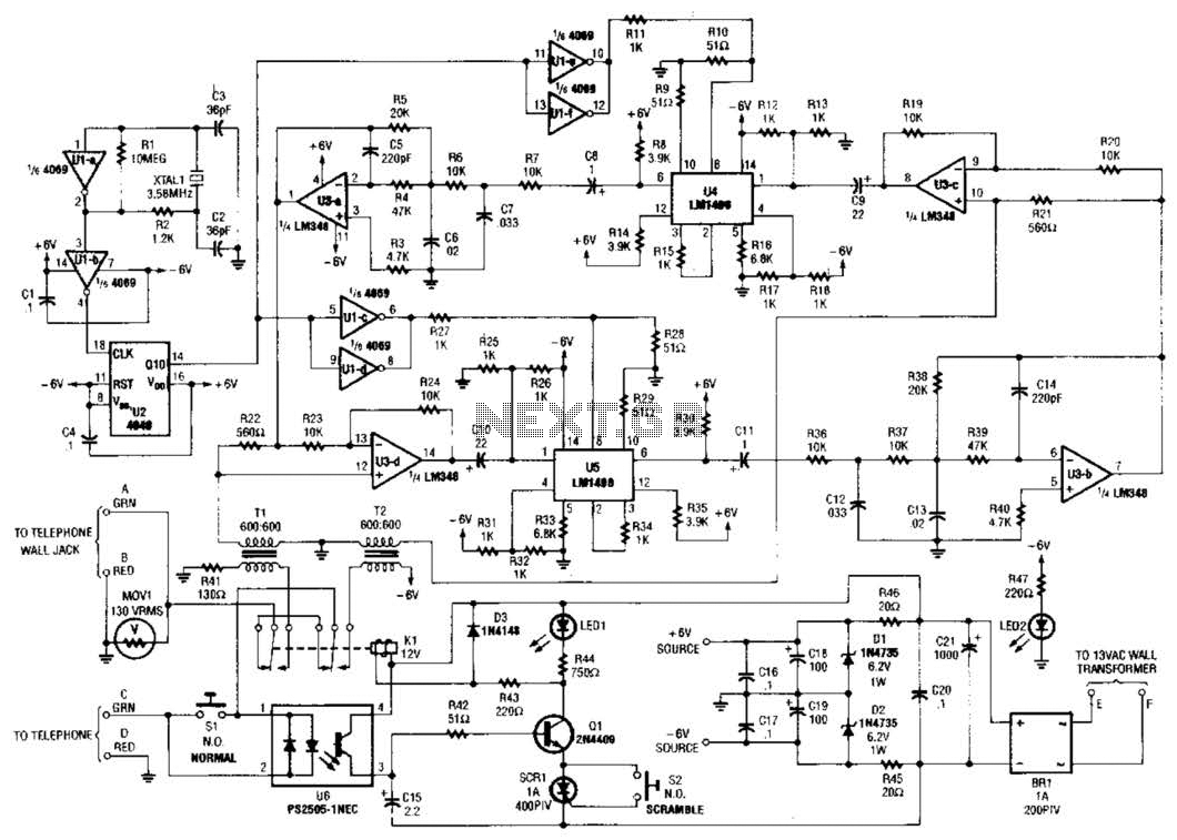
Two hybrids (T1 and T2) are utilized to facilitate a direct connection to a telephone line. This circuit employs a standard speech-inversion algorithm, which inverts the frequency of an audio signal around a central frequency. An LM1496 balanced modulator...
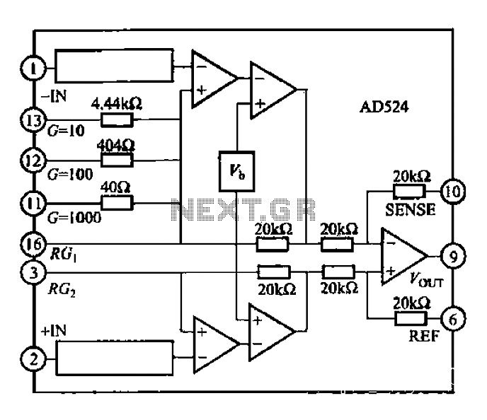
The AD524 is a low-drift instrumentation amplifier characterized by a drift voltage of 0.5 mV and a maximum drift of 25 mV at room temperature. It has low noise performance with a noise level of 0.3 mVp-p in the...
Constantly changing light and sound analog controller circuit 01 The described circuit functions as an analog controller designed to modulate light and sound outputs in a dynamic manner. This circuit typically integrates various electronic components, including resistors, capacitors, transistors, and...
A unit that is often very useful for isolating two stages in sound circuits. This circuit incorporates an amplification unit with a gain of X1. It employs only local negative feedback rather than total negative feedback, resulting in very...