
Zener tester
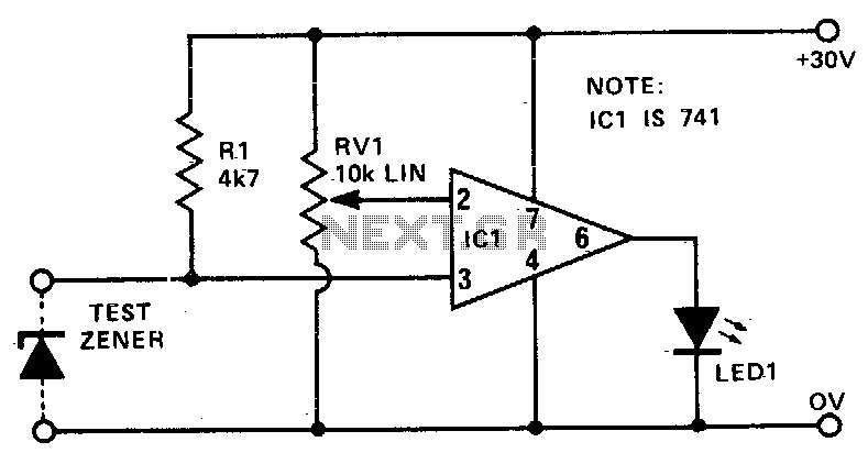
The circuit consists of a basic configuration that includes a zener diode under test, a variable resistor RV1, an LED indicator, and a power supply. The zener diode is connected in reverse bias, allowing it to regulate the voltage when it reaches its breakdown voltage. The variable resistor RV1 is adjusted until the LED indicator lights up, signaling that the zener voltage has been reached.
To enhance the precision of the measurement, the circuit can be modified by integrating a precision potentiometer in place of or in parallel with RV1. This modification allows for finer adjustments and more accurate readings of the zener voltage. The power supply used in the circuit should be chosen carefully to ensure that it can provide a voltage that is sufficient for the zener diode under test, while also being within safe operating limits.
The design can be implemented on a breadboard for prototyping or on a printed circuit board (PCB) for a more permanent solution. Proper attention should be given to the connections and component placements to avoid errors in voltage readings. Furthermore, the circuit could be enhanced with additional features such as a digital voltmeter display for direct voltage readings or a microcontroller interface for automated testing procedures.
This simple yet effective circuit serves as a valuable tool for electronics enthusiasts and professionals alike, facilitating the testing and verification of zener diodes in various applications.This circuit provides a low cost and reliable method of testing zener diodes. RVl can be calibrated in volts, so that when LED 1 just lights, the voltage on pins 2 and 3 are nearly equal. Hence, the zener voltage can be read directly from the setting of RVl. The supply need only be as high a value as the zener itself For a more accurate measurement, a precision pot could be added and calibrated. 🔗 External reference
Related Circuits
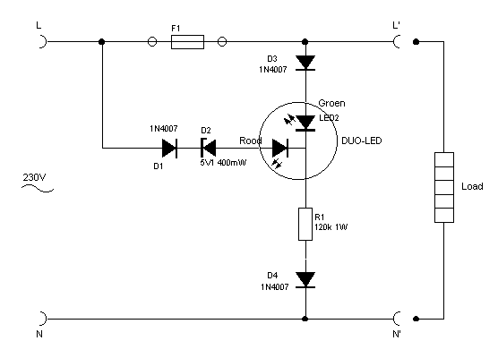
This indicator shows through a dual-LED see if a fuse is intact. The module is designed for 230 V AC. The green LED illuminates when the fuse is still good, the red lights when the fuse is broken. Perhaps...
Latching Continuity Tester. Source: Eldon L. Knight, Tony van Roon A continuity tester is essential on every service bench for testing cables, PC boards, switches, motors, plugs, and jacks. A latching continuity tester is a specialized electronic device designed to...
Testing loudspeakers is covered in some detail in the passive crossover article, but it is irksome at best to have to fiddle about with clip leads and components lying all over the workbench. This simple project is intended to...
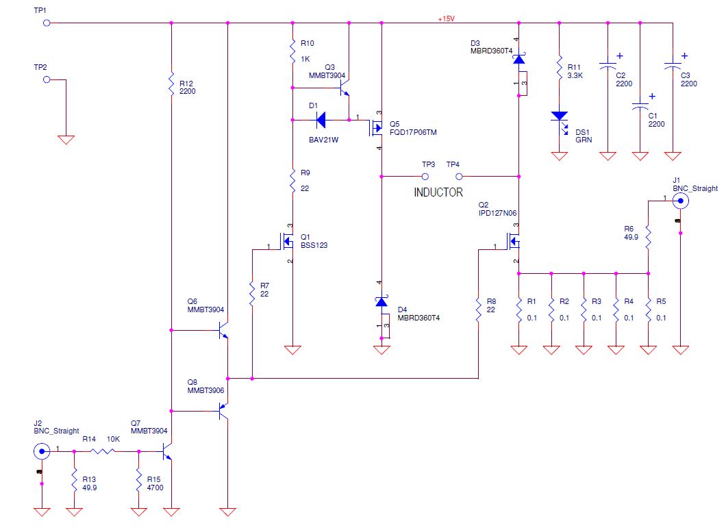
Yes, it does charge the inductor again. Diodes are beneficial as they do not charge the inductor back but dissipate a significant amount of instantaneous power due to the forward voltage drop. One approach would be to monitor the...
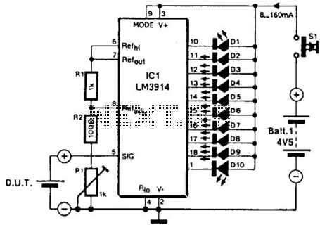
The LM3914A bar graph LED is utilized as a voltmeter for testing batteries. This circuit operates on a 4.5-V battery and compares the battery under test with an internally generated reference, established by resistors R1, R2, and potentiometer P1....
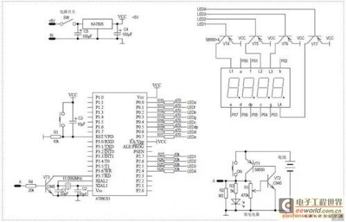
Battery capacity is a crucial indicator of battery quality. There are various methods for testing the volume of rechargeable batteries. One approach involves analyzing the discharge curve of the battery through short-term discharge tests, which can provide a rough...