
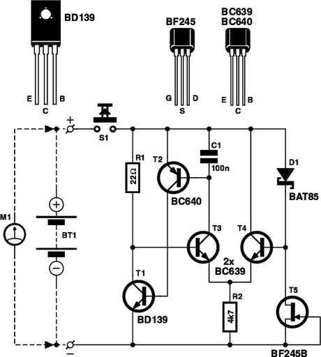
Latching Continuity Tester
A latching continuity tester is a specialized electronic device designed to verify the integrity of electrical connections and circuits. It operates by sending a low-voltage signal through the component under test and determining whether the signal is able to pass through without interruption. This tool is particularly useful in diagnosing faults in cables, printed circuit boards (PCBs), switches, motors, plugs, and jacks.
The device typically includes an LED indicator that illuminates when continuity is detected, providing a clear visual signal to the user. The latching feature allows the tester to maintain its state, indicating continuity even after the test leads have been removed from the circuit. This is especially beneficial for troubleshooting, as it allows the technician to inspect the circuit without needing to hold the tester in place.
In terms of circuit design, a latching continuity tester may consist of a power source, often a battery, a resistor to limit current, a transistor or relay for switching, and an LED for indication. The power source energizes the circuit when the test leads are connected, while the resistor ensures that the current remains within safe limits to prevent damage to sensitive components. The transistor or relay acts as a switch, latching the circuit in the "on" state when continuity is detected, and the LED provides immediate feedback.
This device is indispensable in various applications, including electronics repair, maintenance, and assembly, ensuring that connections are secure and functional before proceeding with further work. Its compact design and straightforward operation make it a valuable tool for any technician or engineer involved in electronic testing and troubleshooting.Latching Continuity Tester. Source: Eldon L. Knight, Tony van Roon A continuity tester is a must on every service bench for testing cables, pcboards, switches, motors, plugs, jacks,. 🔗 External reference
Related Circuits
Is the battery depleted, or is there an issue with the device? This question often arises when a battery-operated device, such as a Walkman, fails to power on. Before seeking professional repair services, it is advisable to first test...
This indicator shows through a dual-LED see if a fuse is intact. The module is designed for 230 V AC. The green LED illuminates when the fuse is still good, the red lights when the fuse is broken. Perhaps...
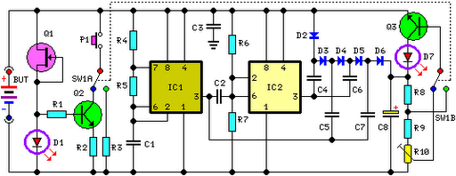
FET Q1 functions as a constant current generator, providing biasing for LED D1 and the base of Q2. This configuration ensures that D1 emits light at a consistent intensity, regardless of the battery voltage, which ranges from 3 to...
A highly beneficial project involving a crystal tester circuit, also known as an xtal tester circuit, constructed with only a few components. The circuit forms an oscillator that will only oscillate if the crystal under test is functioning properly....
This circuit utilizes a single 555 Timer IC along with a small transformer to generate high voltage for testing zener diodes with voltage ratings up to 50VDC. The 555 timer operates in astable mode, with the output from pin...

A balanced Wheatstone bridge controls a JK flip-flop that utilizes an operational amplifier as an interface. This configuration subsequently drives a relay. Resistors R1 through R4 can be increased in value to enhance sensitivity. The circuit employs a balanced Wheatstone bridge,...
Warning: include(partials/cookie-banner.php): Failed to open stream: Permission denied in /var/www/html/nextgr/view-circuit.php on line 713
Warning: include(): Failed opening 'partials/cookie-banner.php' for inclusion (include_path='.:/usr/share/php') in /var/www/html/nextgr/view-circuit.php on line 713