
Loudspeaker Tester
The described circuit serves as a loudspeaker testing and impedance measurement tool, specifically aimed at optimizing frequency compensation networks for woofers and midrange drivers. The circuit incorporates a potentiometer (pot) to adjust resistance values, aiding in the determination of the loudspeaker's actual impedance rather than relying on nominal values. The circuit includes a basic tweeter attenuator, which can be configured with resistors to achieve a desired resistance range, typically from 0 to 20 Ohms.
The main components include a bipolar electrolytic capacitor, which is connected in series with the potentiometer and the speaker, allowing for frequency sweeps to identify optimal impedance characteristics. An optional switch (SW2) can be added to facilitate the use of a larger capacitor value (up to 200uF) if necessary. The circuit also requires a series resistor (approximately 100 Ohms) from the amplifier output to ensure proper signal levels during testing.
Operationally, the user connects the circuit across the speaker and performs a frequency sweep while adjusting the potentiometer to achieve a flat impedance response above the crossover frequency. This process allows for the measurement of voltage across the speaker to establish the correct resistance setting on the potentiometer, which directly correlates to the actual impedance of the loudspeaker.
For accurate results, it is advised to measure the impedance of both the woofer and tweeter, ensuring that the impedance at the crossover frequency matches for optimal performance. The procedure involves connecting the tweeter in parallel with the amplifier and adjusting the pot to match the previously measured voltage, thereby determining the necessary resistance to be used in parallel with the tweeter. This systematic approach simplifies the otherwise complex task of impedance measurement and crossover network design in audio applications.Testing loudspeakers is covered in some detail in the passive crossover article (see Design of Passive Crossovers), but it is irksome at best to have to fiddle about with clip leads and components lying all over the workbench. This simple project is intended to make life that little bit easier when you are trying to determine the optimum frequency compensation network for woofers and midrange drivers.
Of all the components, the pot is most likely to cause problems. The suggested value of 30 Ohms was used in my case because I just happened to have one lying around in my junk box, but they don't seem to be easy to get. A very basic tweeter attenuator may work OK, and the value is not that important. Even a resistance as low as 8 Ohms could be used, with a switchable 8.2 Ohm resistor in series so that the range will be from 0 to 16 Ohms (near enough). I shall leave it to the individual to determine the best way to achieve the required range, which is typically 0 to 20 Ohms.
The switch SW2 and associated 100uF cap is optional, and increases the range up to 200uF - in most cases this won't be necessary though. The caps are all bipolar electrolytics, and this is perfectly OK, since they will not be used at high power, and their sonics are not important (assuming that you can hear the difference anyway).
To use the box, simply connect it across the speaker - mostly you will want the caps and pot in series, so a lead between the two (or even a switch) makes this easy. From the output of suitable small amplifier, place a 100 ohm or so resistance in series with the output.
Sweep the signal frequency across the speaker. Resonance will not be affected, but there will be a "magic" combination of capacitance and resistance that will make the impedance above resonance completely flat. No maths, no spreadsheets, just a quick frequency scan and twiddle a couple of knobs to get the values needed to ensure that the crossover actually will work at the design frequency.
The network derived from the testing will be placed in parallel with the speaker, and prevents the rise of impedance with increasing frequency. This rise is caused by the inductance of the voice coil, and plays havoc with the performance of any passive crossover network.
One of the most difficult measurements to make in audio is impedance, but this is also made relatively simple. Carefully measure the voltage across the speaker at the crossover frequency - this will (of course) be the same as the voltage anywhere else outside of the resonance affected area of the impedance plot.
Disconnect the speaker, and without changing anything, connect the pot (all by itself) instead. Adjust the pot until the voltage is exactly the same as you measured before, when the speaker and parallel network were in place. Disconnect the amp, and measure the resistance of the pot - this is the speaker impedance, and this is the real impedance - not the "nominal" impedance.
It is the actual measured impedance that must be used to calculate the crossover network components. Don't change the frequency from the generator or the amp level just yet ... In many (OK, all) cases, it is highly recommended that the tweeter is also measured for impedance, and a resistance used in parallel so that the impedance at crossover exactly matches that of the woofer or midrange driver. Simply connect the tweeter across the amp, with the pot in parallel. Carefully adjust the pot until the voltage is exactly the same as that measured before (this is where a pot that goes up to about 30 Ohms is useful).
When the voltage is the same, disconnect the amp and tweeter, and measure the setting of the pot. This is the resistance that should be used in parallel with the tweeter to make everything work properly. 🔗 External reference
Related Circuits
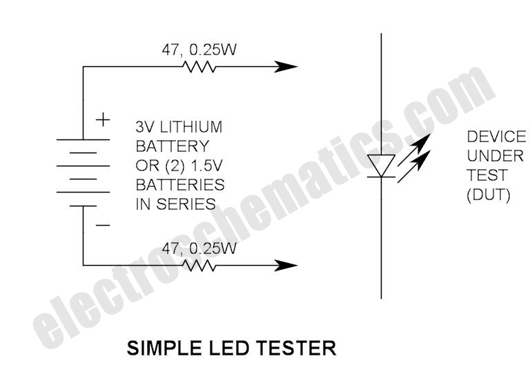
Do not let its extreme simplicity deceive you — this device is useful! Many have been made over the years, and some have even been given away as gifts. Yes, multimeter... A multimeter is an essential instrument in electronics, used...
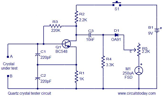
This is a straightforward and cost-effective circuit designed for testing quartz crystals. A Colpitts oscillator is employed using transistor T1. When the crystal is connected between terminals A and B, the circuit generates high-frequency oscillations. These oscillations will only...
This circuit uses the popular and easy to find LM3914 IC. This IC is very simple to drive, needs no voltage regulators (it has a built-in voltage regulator) and can be powered from almost every source. When the test...
This is a simple servo tester which will comprehensively test the capabilities of almost any modern servo. It has two pushbuttons, CENTRE and SWEEP and a potentiometer which works as follows: - CENTRE Does exactly that, centers the servo,...
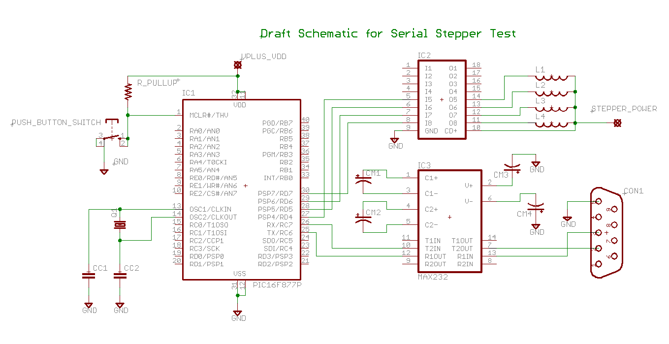
Determining the identification of drive wires on a unipolar stepper motor, which is commonly found in surplus or salvaged equipment. The platform utilized is a PIC16F877A microcontroller programmed with BoostC, interfaced via RS232 to a PC running a terminal...
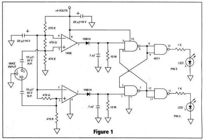
Many things can go wrong in a modern recording studio, but few are as difficult to track down as reversed microphone polarity. When a microphone is placed in front of a sound source, a positive pressure on its diaphragm...