
old dick smith catalog mains led circuit

The input data indicates a lack of sufficient information regarding the specifics of the electronic schematic or circuit design being discussed. The mention of a "catalog" suggests the need for a reference source that provides detailed specifications or components relevant to the project.
In electronic design, a catalog typically includes information on various components such as resistors, capacitors, integrated circuits, and other essential elements that are critical for creating an effective circuit. The absence of an appropriate catalog can hinder the design process, as engineers rely on these resources to ensure compatibility and functionality of the components used in their circuits.
When developing a circuit, it is essential to define the schematic clearly. This involves specifying the power supply requirements, the type of inputs and outputs needed, and the desired functionality of the circuit. A comprehensive schematic should include the following elements:
1. **Power Supply**: Identification of the voltage and current ratings necessary for the circuit operation, as well as any required voltage regulation components.
2. **Component Specifications**: Detailed descriptions of each component, including their values (e.g., resistance, capacitance), types (e.g., ceramic capacitors, bipolar junction transistors), and configurations.
3. **Connections**: Clear representation of how components are interconnected, including wire types, PCB traces, or breadboard connections.
4. **Functional Blocks**: If applicable, the schematic should illustrate functional blocks or sections of the circuit, such as amplifiers, filters, or microcontroller sections, and how they interact with each other.
5. **Testing Points**: Inclusion of test points in the schematic allows for easier troubleshooting and verification of circuit functionality during development.
6. **Grounding and Shielding**: Proper grounding techniques and shielding considerations should be outlined to minimize noise and interference, which are critical for circuit performance.
A well-structured electronic schematic serves as a blueprint for the circuit design process, guiding engineers through the assembly and testing phases. Without a reliable catalog or reference material, it becomes increasingly challenging to ensure that the circuit will function as intended, highlighting the importance of thorough documentation and component understanding in electronic engineering.hi everyone! my first post (for quite a while! lol!). i obviously haven`t still got an old enough tricky dicky catalog! in the data section there used .. 🔗 External reference
Related Circuits
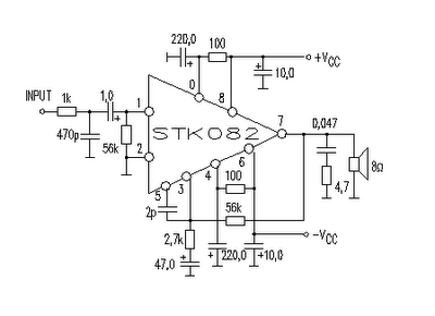
This amplifier circuit is suitable for home power audio devices. The STK082 amplifier specifications suggest that it can operate with supply voltages of up to ±43V. However, it is advisable to use no more than ±25V for 8-ohm loads,...
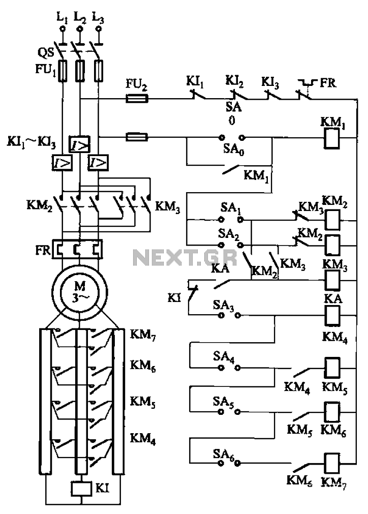
The circuit depicted in Figure 3-168 utilizes a controller for speed grading and reversing control. A reverse brake is connected to the rotor circuit through an overcurrent relay, labeled KI, for control. The current relay KIi to KI3 serves...
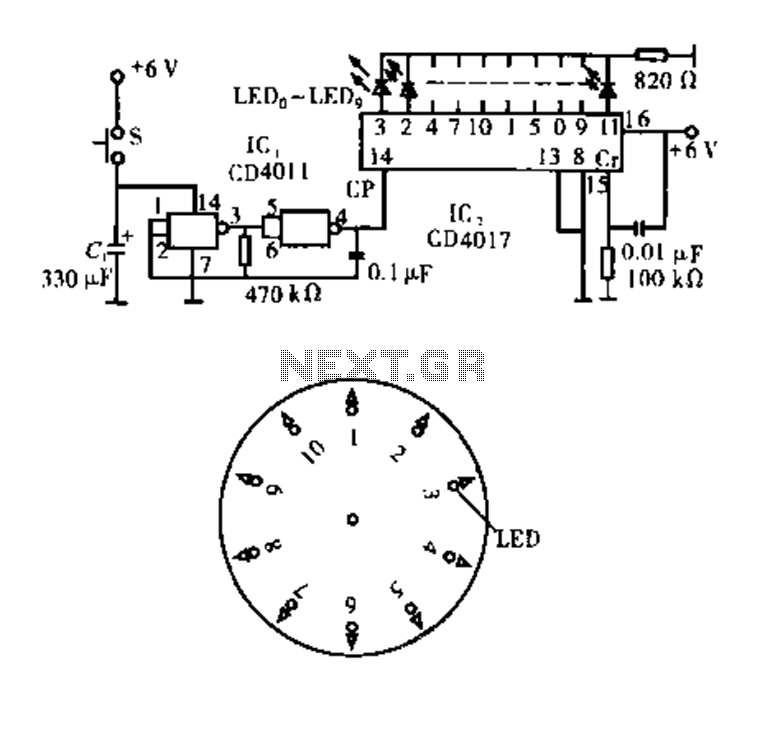
Dot Award. This circuit is tested and functional. The circuit consists of two integrated circuits (ICs). IC1 serves as a pulse source, activated by a momentary button switch (S). When the button is pressed, it charges capacitor C1, which...
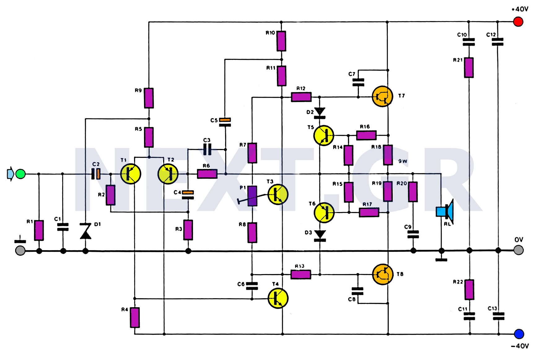
This amplifier is designed with the following specifications: distortion less than 0.1% at full power of 100W even at 20KHz, with power attributed to an extended bandwidth. The output transistors are protected against short circuits, and the power supply...
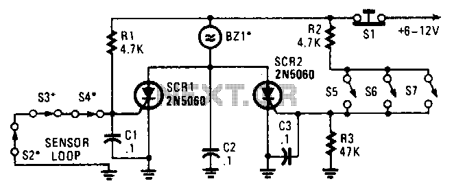
Two SCRs are utilized with two sensor loops. One loop employs series switches, while the other loop employs parallel switches. When a switch is actuated, the SCR is triggered. The alarm is designed to be a non-interrupting type. The circuit...
Motor Bike Headlight Controller Circuit. This circuit automatically turns a motorcycle's headlight on and off, independently of both the light and ignition switches, provided the battery is fully charged. The first stage... The motorcycle headlight controller circuit is designed to...