
ZN414 portable Receiver

The receiver circuit leverages the capabilities of the ZN414 or MK484 IC, which is well-regarded for its simplicity and effectiveness in medium wave reception. The design emphasizes the importance of using a correctly tuned coil and capacitor, which are critical for achieving the desired frequency range and sensitivity. The incorporation of a voltage regulator ensures that the IC operates within its optimal voltage range, enhancing performance stability and preventing overload conditions.
The audio amplification section utilizes a classic 741 op-amp in an inverting configuration, which allows for straightforward gain control while maintaining audio fidelity. The use of complementary transistors (BC109C and BC179) for current boosting is a practical approach to drive the speaker effectively, ensuring that the output is robust enough for clear sound reproduction.
The tuning mechanism, which can be sourced from an existing radio, not only simplifies the build process but also leverages proven components that enhance performance. The overall design is compact, making it suitable for integration into a small enclosure, as demonstrated by the prototype constructed with wood. The inclusion of a potentiometer for selectivity allows users to fine-tune the receiver's response to various signal strengths, making it adaptable to different listening environments.
In conclusion, this medium wave receiver circuit exemplifies an efficient and effective design approach, utilizing readily available components and demonstrating solid performance characteristics, making it an excellent project for electronics enthusiasts.Designed around the popular ZN414 IC this receiver covers the medium wave band band from approximately 550 to 1600 KHz with the values shown. The coil and tuning capacitor may be taken from an old MW radio to save time. The ZN414 IC, has now been replaced by the MK484. The integrated circuit is a 3 pin, tuned radio frequency circuit, and incorpora tes several RF stages, automatic gain control and an AM detector. It is easily overloaded and the operating voltage of th IC is somewhat critical to achieve good results. In this circuit a small voltage regulator is built around the BC108B transistor, four 1N4148 diodes, the 2k7 and 10k preset resistor and the 820R resistor.
The 10k pot acts as a selectivity control for the whole receiver, controlling the operating voltage for the ZN414 (or MK484). If you live in an area that is permeated with strong radio signals, then the voltage may need to be decreased.
I found optimum performance with a supply of around 1. 2 volts. The audio amplifier is built about an inverting 741 op-amp amplifying circuit. Extra current boost is provided using the BC109C / BC179 complementary transistor pair to drive an 8 ohm loudspeaker. The voltage gain of the complete audio amplifier is around 15. The audio output of the complete receiver is really quite good and free from distortion. I may provide a sound sample later. Click here to see a picture of my prototype. I used a small wooden enclosure and the complete tuning assembly from an old radio. 🔗 External reference
Related Circuits
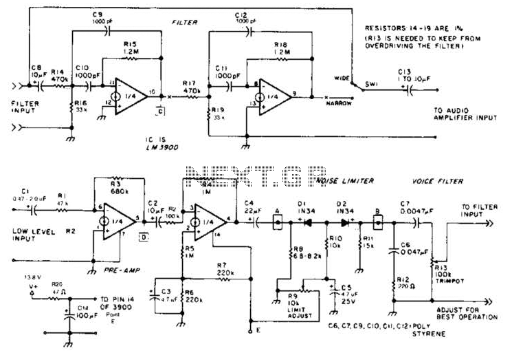
The noise limiter circuit features a preamplifier clipper and a switchable audio bandpass filter. Audio levels ranging from 5 to 50 mV are amplified in a preamplifier to several volts peak-to-peak, which are then sent to a clipper and...
This is a compact three transistor regenerative general coverage receiver with fixed feedback. It's based on the principle of the ZN414 only much higher coverage. The sensitivity and selectivity is relatively good (especially on the LF and MW bands)...
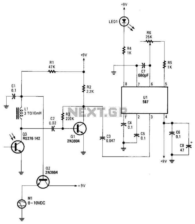
Q3 is an infrared (IR) phototransistor that reacts to a modulated IR beam. Q1 amplifies the alternating current (AC) component of the IR beam. Q2 drives a meter, providing a relative indication of the strength of the light beam,...
The ADM3251E is a transceiver that features high-speed operation, 2.5 kV full isolation, and a single channel for RS-232/V.28 communication. This device operates from a single 5 V power supply. The ADM3251E transceiver is designed for robust communication in environments...
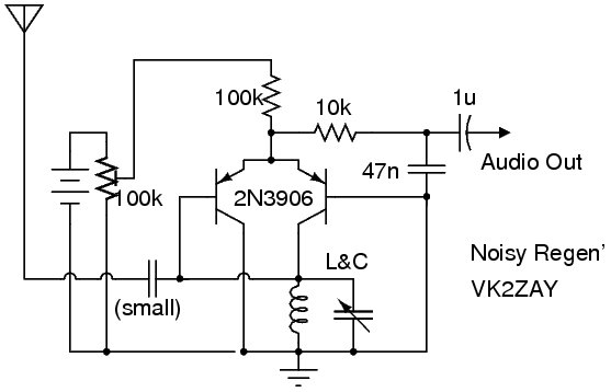
The following circuit illustrates a Noisy Regenerative Receiver Circuit Diagram. Features include a Noisy Regenerative Receiver Circuit, which simplifies the process of... The Noisy Regenerative Receiver Circuit is designed to amplify weak radio frequency signals while also incorporating a regenerative...
The operation of this receiver is analogous to human perception. Humans perceive colors and respond based on what they observe. Similarly, phototransistors react to the intensity of infrared light directed at them. The key distinction is that humans possess...