
RF drive audio oscillator

The described circuit utilizes the 555 timer in astable mode, which enables it to generate a continuous square wave output. The frequency of the oscillation is primarily influenced by the resistive and capacitive components connected to the timer. Resistor R1 is connected in series with the variable resistor RP1, which provides the ability to adjust the resistance and consequently the frequency of the output signal. The capacitor C1 is connected in parallel with the resistors and plays a critical role in determining the timing intervals of the oscillation.
In practical applications, the frequency range of 600 Hz to 20 kHz is suitable for various audio signal generation purposes, including tone generation, sound synthesis, and modulation applications. The ability to adjust RP1 allows for fine-tuning of the output frequency, making the circuit versatile for different audio applications.
The circuit can be implemented on a breadboard or a printed circuit board (PCB) for stability and durability. It is essential to ensure that the power supply voltage is within the operating range of the 555 timer, typically between 4.5V to 15V, to ensure reliable operation. Additionally, proper bypass capacitors should be included to filter any noise from the power supply, enhancing the performance of the oscillator.
Overall, this 555 timer-based audio oscillator circuit is a fundamental design that serves as an excellent introduction to oscillator design and audio signal processing, with numerous applications in electronic projects and sound-related endeavors.As illustrated, 555 and Rl, RPl, C1 controllable audio oscillator and other components, f 1.44/(R1 + 2RP1) C1, the parameters shown in the frequency between 600Hz ~ 20kHz, can be adjusted RP1 selected.
Related Circuits
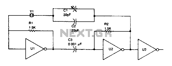
TTL inverter stages, U1 and U2, are cross-connected with a crystal Y1. A resistor in each stage biases the normally digital gates into a region where they operate as amplifiers. Inverter stage U3 is used as a buffer. The circuit...
Most blog posts involve short 3-4 hour projects or hacks that are built for learning and enjoyment. It was time to develop something more substantial. The project described appears to focus on creating electronic circuits that can be completed within...
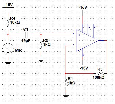
This lab will demonstrate the theory and operation of non-inverting amplifiers as well as their practical application to amplify the signal of a microphone. A non-inverting amplifier will be constructed to increase the output signal of a microphone, which...
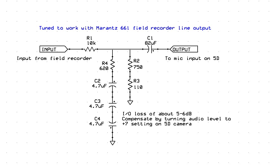
Enhancing the audio quality of the Canon 5D Mark II to achieve usable production audio involves several key steps. The initial phase of this engineering project focuses on data collection, specifically measuring the input frequency response of the 5D....
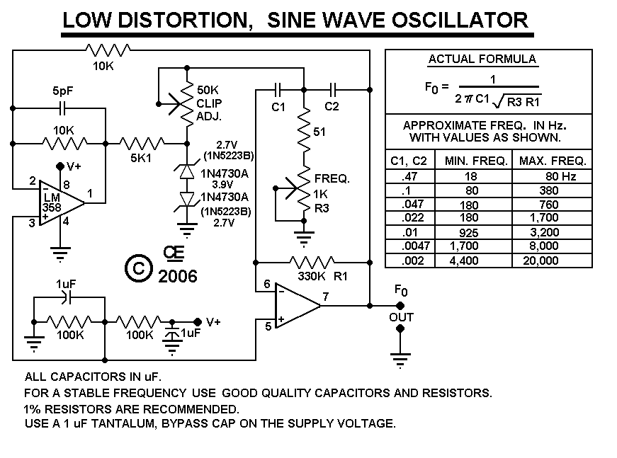
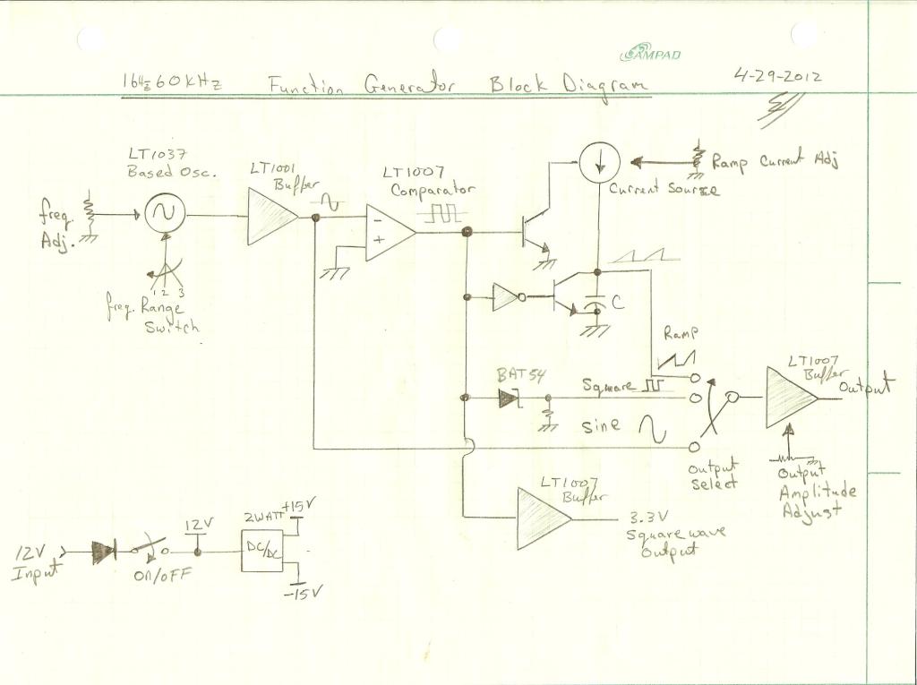
After constructing the device, adjust the frequency to the desired level using the "Frequency Control." Then, utilize an oscilloscope to fine-tune the waveform for optimal performance with the "Clip Control." The sharp rise and fall times of square waves...
Electronics Circuits Reference Archive Audio preamplifier circuits. There are thousands of preamplifier circuits. Here are three that are somewhat different and have garnered interest. Intercom preamp: A very convenient way of making an intercom system. Audio preamplifiers are essential components...