
Audio preamplifier circuits

Audio preamplifiers are essential components in audio signal processing, serving to amplify low-level audio signals before they are fed into power amplifiers or other processing equipment. The following details outline three unique preamplifier circuits, with a particular focus on the intercom preamp.
The intercom preamp circuit is designed to enhance audio signals transmitted between intercom units. It typically consists of a low-noise operational amplifier (op-amp) configured in a non-inverting configuration to ensure minimal signal distortion and high input impedance. This configuration allows the circuit to accept signals from various audio sources, such as microphones or audio playback devices.
Key components of an intercom preamp may include resistors for setting the gain, capacitors for coupling and decoupling signals, and possibly a power supply circuit to ensure stable operation. The gain of the preamp can be adjusted by varying the feedback resistor values, allowing customization based on the specific requirements of the intercom system.
Additionally, the circuit may incorporate filtering stages to eliminate unwanted noise and enhance signal clarity, ensuring that the audio output is clear and intelligible. Proper grounding and layout considerations are crucial in minimizing electromagnetic interference, which can degrade audio quality.
In summary, the intercom preamp circuit exemplifies a practical application of audio preamplification, showcasing the importance of circuit design in achieving high-quality audio signal transmission in intercom systems.Electronics Circuits Reference Archive Audio preamplifier circuits There are thousands of pre-amplifier circuits. These are three which have interested me and are a little different. Intercom preamp A very convenient way of making an interc.. 🔗 External reference
Related Circuits
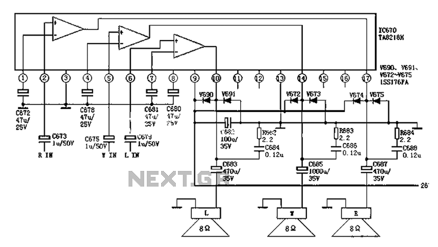
The audio circuit depicted in the figure is commonly utilized in color television systems. The pin functions and reference voltages for the TA8218AH are as follows: Pin 1: 1.9V - inverting input; Pin 2: 2.1V - R-channel audio signal...
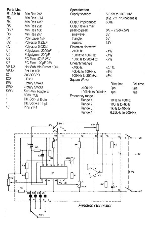
This generally results in a square wave if the frequency of oscillation is low enough relative to the amplifier's bandwidth. The schematic of a crystal-controlled oscillator features a low-frequency sine wave oscillator characterized by low distortion, wideband operation, and...
The first application has to be a stereo power amp, since that's what I built using two prototype modules. The reasons for this choice are twofold - a good high powered stereo amp is always useful, and it was important...
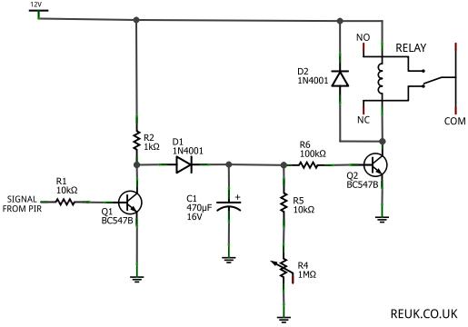
The focus is on 12 Volt DC powered PIR sensors and their associated circuits, which can be directly powered by a 12 Volt battery charged through renewable energy sources such as wind or solar. This article examines how the...
This circuit was submitted by Graham Maynard from Newtownabbey, Northern Ireland. It has an exceptionally good high frequency response, as demonstrated by applying a 100kHz squarewave to the input. Response graphs were produced using Tina Pro to highlight these...
This article is intended for individuals interested in constructing their own car amplifier. The fundamental calculations will be discussed below. Understanding these concepts will enable the construction of a car amplifier independently. The challenge in designing a car power...