
Intelligent thermostat temperature sensor LM75 circuit diagram consisting

The described thermostat controller circuit operates using an LM75 temperature sensor, which communicates over the I2C bus. The LM75 is a digital temperature sensor that provides accurate temperature readings and can be configured to operate in various modes, including alert modes for temperature thresholds.
In this circuit, the LM75 outputs a digital signal that represents the ambient temperature. This output is connected to the base of the 2N3904 NPN transistor, which functions as a switch. When the temperature reading exceeds a pre-defined threshold, the LM75 sends a high signal to the transistor. The 2N3904, when activated, allows current to flow from its collector to its emitter, thereby energizing the relay coil.
The relay is essential for controlling the power to the thermostat. It acts as an electrically operated switch that can handle higher voltage and current levels than the LM75 and 2N3904 can manage directly. The relay contacts are connected to the power supply of the heating or cooling unit, allowing the thermostat to turn these devices on or off based on the ambient temperature readings.
This configuration allows for effective climate control by automatically adjusting the heating or cooling system in response to temperature changes, ensuring a comfortable environment. The use of the I2C bus interface simplifies the wiring and communication between the temperature sensor and the controlling circuit, making the design more efficient and scalable for various applications. As shown by simple smart temperature sensors based on I2C bus interface configured as shown thermostat controller circuit. LM75 through 2N3904 transistor to drive the relay coi l K, according to the measured level of ambient temperature to control the thermostat off power to achieve climate control.
Related Circuits

The circuit comprises an N-MOSFET voltage follower (T1, common drain) and a current source (T2, NPN Darlington). The current source is set to 2.2 Amps. With a supply voltage of 40V, the circuit can deliver approximately 17W into an...
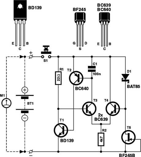
Determining whether a battery is empty or if there is a fault with a device can be challenging when a battery-powered device, such as a Walkman, fails to power on. Before seeking professional repair, it is advisable to test...

The following circuit illustrates an AM/Shortwave Radio Frequency Calibrator Circuit Diagram. This circuit is based on the 74LS93 IC. Features: The .. The AM/Shortwave Radio Frequency Calibrator Circuit utilizes the 74LS93 integrated circuit, which is a 4-bit binary counter. This...

CB85-10 leakage protection circuit diagram, T for the trip coil, SB is the test button, Ri is simulated human resistance. The CB85-10 leakage protection circuit is designed to enhance safety by detecting leakage currents and disconnecting the electrical supply to...

The circuit illustrated in the schematic diagram below allows for the visualization of the direction and shaft rotation of a stepper motor on an LED display. Instead of employing a digital rotation encoder as an input, this circuit utilizes...

The RS-232 system connection is faster and easier, but the distance is limited. Therefore, this project involves using an RS-485 system with an RS-232 to RS-485 converter. The RS-232 to RS-485 converter project aims to extend the communication range and...