
CB85-10 leakage protection circuit

The CB85-10 leakage protection circuit is designed to enhance safety by detecting leakage currents and disconnecting the electrical supply to prevent electric shocks. The circuit includes a trip coil (T), which is the actuator responsible for opening the circuit when a leakage is detected. The test button (SB) allows users to simulate a fault condition to verify the functionality of the protection circuit. The simulated human resistance (Ri) represents the resistance of a human body, which is critical for determining the threshold at which the circuit will activate.
In this schematic, the trip coil is connected to a relay that interrupts the power supply when a leakage current exceeds a predetermined level. The test button is strategically placed in the circuit to facilitate routine testing, ensuring that the leakage protection system is operational. The simulated human resistance is typically set to approximate the resistance of a person under fault conditions, allowing the circuit to react appropriately to real-world scenarios.
The circuit operates under the principle of differential current sensing, where the current flowing through the live and neutral wires is continuously monitored. If a difference in current is detected, indicative of leakage, the trip coil is energized, causing the relay to open and disconnect the load. This design emphasizes reliability and safety, making it suitable for various applications in residential and commercial electrical systems. Regular testing via the test button is essential to maintain the integrity of the leakage protection mechanism. CB85-10 leakage protection circuit diagram, T for the trip coil, SB is the test button, Ri is simulated human resistance
Related Circuits
A fingerprint door lock system is being considered for implementation. The primary component is a fingerprint reader that, upon recognizing a valid fingerprint, will instruct an Arduino microcontroller to activate a locking mechanism for a predetermined duration. The locking...

A device that conducts electric current and converts electrical energy into another form. Power consumed by a device or circuit while performing its function can be represented by a resistor and capacitor. The capacitor in the load circuit represents...
Operating radio transmitters without a license is illegal in most countries, so caution is advised with transmitter circuits. This FM low-power circuit is designed to operate within the 87-108 MHz band II, providing a range of approximately 20 to...
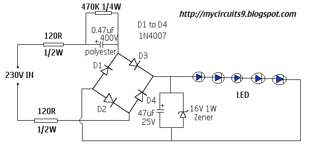
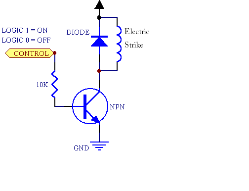
This document presents a 230V LED driver circuit that operates without a transformer. The circuit utilizes five LEDs, although the number can be increased as desired. The absence of transformers significantly reduces both the cost and size of the...
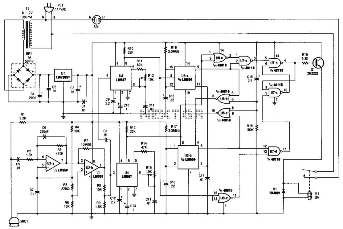
The whistle switch features two tone detectors, each based on an LM567 tone decoder, requiring minimal additional components. It is designed to respond to two or more occurrences of a specific tone or sequence of tones within a defined...
This digital DIY tachometer for bicycles utilizes two reed switches to gather speed information. The reed switches are positioned near the wheel rim, where permanent magnets are mounted on the wheel spokes. As the spokes rotate, the magnets pass...