
Basic circuit diagram connection of signal and power ISO103

The ISO103 is an isolated signal and power supply circuit that requires careful attention to bypass filtering at each power supply terminal to ensure stable operation and minimize noise. The bypass filters are essential for maintaining signal integrity, particularly in applications where high-frequency signals are present. When the output current of the isolated power supply exceeds 15mA, an external filter should be implemented on the +Vcc2 pin to further mitigate ripple effects and stabilize the power supply.
The recommended inductor value of 10 µH for L1 is crucial in forming a low-pass filter that attenuates high-frequency noise. The selection of capacitors is equally important; the values of 1 µF and 10 µF for Co, depending on the specific configuration, help in smoothing out voltage fluctuations and ensuring a stable power supply to the circuit.
The isolation rectifier output (Vcc1) serves as a critical point in the circuit, providing power to the amplifier input supply pins (Vc). Both Vcc1 and Vc can benefit from additional filtering, either through ripple filters or calibrators, to enhance performance.
In terms of TTL logic levels, proper connections are essential for reliable operation. The high state on pin 13 indicates a logical '1', while pin 15 must be tied to ground to establish a reference point for the circuit. This configuration is vital for ensuring that the circuit operates within the specified logic levels and behaves predictably under varying conditions.
Overall, the design considerations outlined above contribute to the reliable functioning of the ISO103 circuit, making it suitable for applications requiring isolated signal and power supply management. As shown for the basic connection circuit ISO103 signal and power supply. Each power supply terminal must have a bypass filter. When isolated power supply output current is gre ater than 15mA, we recommend the use of such power pin of + Vcc2 pin external filter. -type filter can reduce the ripple current, take L1 10 H. Isolation rectifier output pin ( Vcc1) and amplifier input supply pins ( Vc) can be attached to the ripple filter or calibrator. Filter element parameters: When 0 L0 10 H, Co 1 F, when L0 10 H time, Co 10 F. TTL open or take 13 feet high, 15 feet as the ground can not.
Related Circuits

This is a solar-powered flasher designed to deter nocturnal animals such as bats and cats from farmyards or residential premises. The device features a bright multicolored light. The solar-powered flasher operates by utilizing a solar panel to harness sunlight, converting...
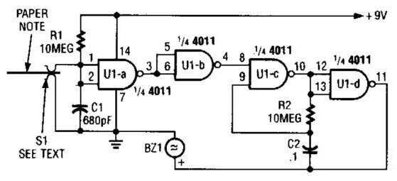
This device prevents paper notes and memos from being overlooked. A paper note placed between two fingers made of a conducting material (metal or conductive plastic) breaks the circuit, allowing pair 1 of Ul-a to go high. The goal...
Electrical signals travel along the neurons in the brain and body, continuously transmitting information throughout the complex system. Without these signals, the body would function like a plant, with different parts unaware of each other's conditions, making animal life...
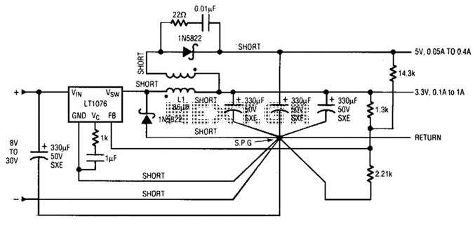
Input voltages can range from 8 V to 30 V. The load range for the 5 V output is from 0.05 A to 5 A, while the load range for the 3.3 V output is from 0.1 A to...
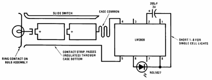
The schematic presented below illustrates the Flashlight Finder circuit diagram utilizing the LM3909, a monolithic oscillator specifically designed for flashing Light Emitting Diodes (LEDs). The Flashlight Finder circuit employs the LM3909 integrated circuit, which is capable of generating a series...
This is a very basic infrared detector/emitter circuit. One major downside of this circuit, is that ambient infrared light will interfere with its detecting obstacles. The described circuit functions as a basic infrared (IR) detector and emitter system, commonly utilized...