
Basic IR Detector/Emitter

The described circuit functions as a basic infrared (IR) detector and emitter system, commonly utilized in various applications such as obstacle detection, remote control systems, and simple proximity sensors. The core components typically include an infrared LED (emitter) and a photodiode or phototransistor (detector).
In operation, the infrared LED emits light in the infrared spectrum, which is not visible to the human eye. When this emitted light encounters an object, it reflects back towards the detector. The photodiode or phototransistor is sensitive to the reflected IR light and generates a corresponding electrical signal. This signal can then be processed to determine the presence or distance of an object.
One significant limitation of this basic design is its susceptibility to ambient infrared light sources, such as sunlight or artificial lighting, which may interfere with the detection of obstacles. This interference can lead to false readings or reduced sensitivity, as the detector may respond to the background IR signals rather than solely the reflected light from the intended object.
To enhance the performance of this circuit, various modifications can be considered. For example, incorporating a modulation technique where the IR LED is pulsed at a specific frequency can help differentiate between ambient light and the signal from the reflected IR light. Additionally, using filters that only allow specific wavelengths of light to reach the detector can minimize interference from unwanted sources.
Circuit design may also include amplifying stages to boost the signal from the detector, enabling better detection capabilities. Moreover, integrating a microcontroller can facilitate advanced processing, allowing for more sophisticated obstacle detection algorithms and the ability to adjust sensitivity dynamically based on environmental conditions.
Overall, while this basic infrared detector/emitter circuit serves fundamental applications, enhancements and careful consideration of ambient light conditions are crucial for improving reliability and accuracy in real-world scenarios.This is a very basic infrared detector/emitter circuit. One major downside of this circuit, is that ambient infrared light will interfere with its detecting obstacles. 🔗 External reference
Related Circuits
A diode for alternating current is a trigger diode that conducts current only after the DIAC reaches the breakdown voltage. The breakdown voltage of the DIAC is 30 V. A DIAC, or Diode for Alternating Current, is a semiconductor device...

Figure C1 and C2 depict a 22 pF capacitor connected to a 32 MHz crystal oscillator circuit, which utilizes a quartz crystal for standard operation. Capacitors C3 and C4, each rated at 15 pF, are connected to a 32.768...

Two simple 12V DC motor speed controllers can be constructed for a minimal cost. These controllers take advantage of the principle that the rotational speed of a DC motor is directly proportional to the average value of its supply...
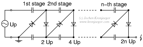
The Greinacher doubler circuit (a) transforms a grounded AC voltage (peak voltage Up) into symmetrical DC voltages of 1x Up each, thus producing 2x Up between outputs. If the input voltage is already symmetrical (e.g. as in an Obit),...

A method for determining altitude involves the use of barometric pressure; however, it presents certain challenges. The relationship between pressure and altitude is not linear but rather complex, a concept developed by the army in the 1930s. The equation...

The Kelvin scale version reads from 0 to 1999 K theoretically, and from 223 K to 473 K actually. The 26 kΩ resistor brings the input within the ICL7106 common-mode voltage range; two general-purpose silicon diodes or an LED...