
Binary gain step circuit diagram by the PGA205

The binary gain step circuit utilizing the PGA205 operational amplifiers is designed to provide a versatile range of gain settings from 1 to 64, making it suitable for various signal processing applications. The configuration of two PGA205 devices in cascade allows for the multiplication of their individual gains, enhancing the overall gain flexibility of the circuit.
In this circuit, each PGA205 can be independently configured to achieve specific gain values, which are then multiplied together to determine the total gain of the system. This allows for precise control over the amplification process, enabling the circuit to adapt to different input signal levels effectively.
The PGA205 is a programmable gain amplifier that features a range of gain settings that can be controlled digitally. This capability is essential for applications requiring dynamic adjustment of gain in response to varying signal conditions. The gain settings can typically be adjusted through a digital interface, allowing for integration with microcontrollers or digital signal processors (DSPs).
The schematic of the circuit will typically include power supply connections, input and output terminals, and control lines for setting the gain of each PGA205. Capacitive coupling may be employed at the input and output stages to block DC offsets and ensure that only the AC component of the signal is amplified. Additionally, feedback resistors may be used to stabilize the gain and improve linearity across the operational range.
In summary, the binary gain step circuit using two PGA205 amplifiers in cascade configuration provides a robust solution for applications requiring adjustable gain with high precision and flexibility. The design facilitates easy integration into larger systems where gain control is necessary for optimal performance. Binary gain step circuit is shown by PGA205 constituted a gain range of 1 to 64. The circuit uses two PGA205 cascade with a total gain of the circuit is the product of a two-st age gain, that is G G1G2. Each PGA205 gain setting shown in Figure.
Related Circuits
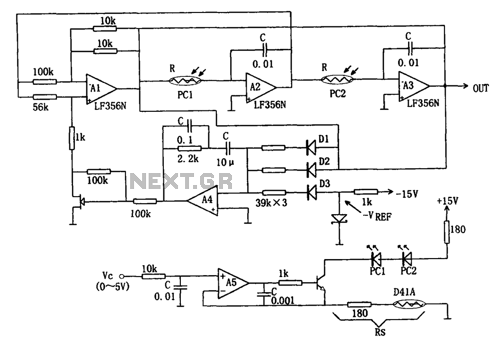
The wideband sinusoidal voltage-controlled oscillator circuit is designed such that the oscillation frequency is determined by an integrating resistor R and a capacitor C. The voltage-controlled oscillator is constituted by the applied control voltage Vc and a control resistor...
This circuit utilizes an MC3392 low-side protected switch in conjunction with an MC1455 timing circuit to create a dimmer control for automotive instrumentation panel lamps. The brightness of incandescent lamps is adjustable through Pulse Width Modulation (PWM) applied to...
This analog switch circuit is designed to switch an analog line on or off. It consists of two analog switches in integrated circuit (IC) form that are controlled by two pushbuttons. The described analog switch circuit utilizes two integrated analog...
The circuit described is a photoelectric receiver amplifier designed to amplify the electrical signals generated by photodiodes or phototransistors in optoelectronic devices. When the intensity of incident light varies, the photosensitive device generates a corresponding voltage or current. The...
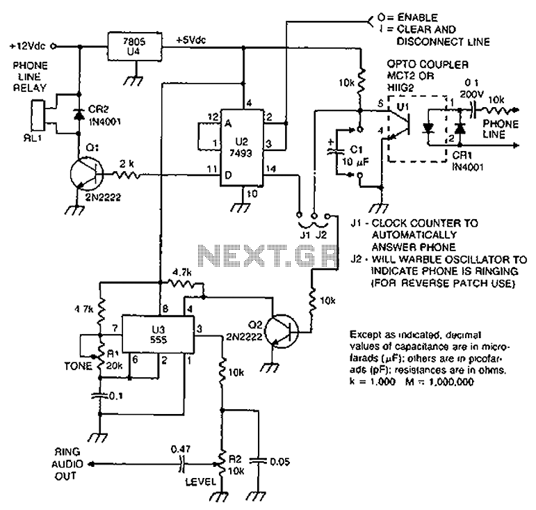
Check the loop circuit for an automatic telephone answering system or a tone generator for use in reverse automatic repair. The loop circuit in an automatic telephone answering system is designed to detect incoming calls and activate the answering mechanism....
The application that we propose is a simple filter that limits the acoustic region (20-20000Hz) to the region 20-100Hz. With the manufacture proposed, an active filter can be created to drive a loudspeaker for very low frequencies. This allows...