
R-40-16 ultrasonic receiver circuit

The described circuit operates as a remote control system utilizing a series of transistors for signal amplification and relay control. The multi-stage amplifier, consisting of transistors VT1 to VT3, is designed to boost the weak signal from the transmitter, ensuring reliable operation even at low signal levels. The output from this amplifier is a square wave pulse, which is essential for the bistable circuit operation.
The bistable circuit, controlled by transistors VT4 and VT5, functions as a flip-flop, allowing the circuit to maintain its state until a new trigger pulse is received. The trigger pulse is generated when the transmitter sends a signal, which is coupled through capacitors G and C to transistor VT4. This transistor is responsible for initiating the state change in the bistable circuit. When activated, VT4 allows current to flow, thus turning on VT5 and VT1, which switch the state of the relay K.
The relay K acts as a switch for the connected load, enabling or disabling it based on the state of the bistable circuit. When VT5 is turned off, VT7 is also deactivated, which releases the relay and maintains its state until a new pulse is received. The circuit's design allows for a seamless transition between states, ensuring that the load can be controlled remotely with minimal delay.
The use of transistors in this circuit provides advantages such as low power consumption and high reliability. Additionally, the circuit can be adapted for various applications, including remote control of lighting systems, motors, or other electrical devices, making it a versatile solution for automation needs. Circuit consists VTl. ~ VT7 and other components. Since receiving the signal emitted by the transmitter is very weak emblem, the circuit uses multi -stage amplifier, the output square wave pulse signal to control VT5,1n fly and associated components work status bistable circuit, the transistor VT4 each turned once ( transmitter emits a) trigger signal by G, C fed to the bistable circuit a trigger pulse, VT5, V; 113 a reversal times. When VTfi; when is turned off from, VT5, VT7 closing, relay K release amnesty and maintained. When the next pulse arrives, VT6 by the conduction is turned off. VT7 conduction, the relay pull-K, control the work load. This circuit can be used for remote control of various electrical switches.
Related Circuits
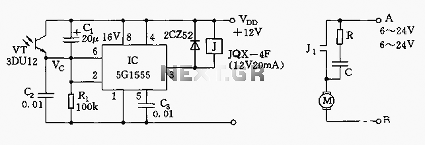
The control circuit consists of an NE555 timer and a phototransistor, along with resistors R1, capacitors C1 and C2, among other components. The photodiodes 3DU12 respond to sunlight by decreasing their resistance, which causes the voltage at the 555...
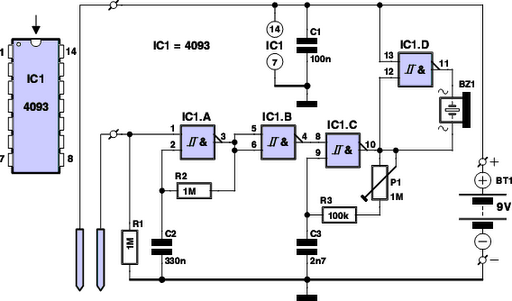
Have you ever observed the stairs to an upper story in your house transform into a waterfall? Or perhaps you returned home to find your aquarium fish attempting to swim across the carpet? For your sake, it is hoped...
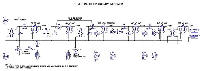
A tuned radio frequency (TRF) receiver is a radio receiver typically consisting of multiple tuned radio frequency amplifiers followed by circuits for detecting and amplifying the audio signal. A three-stage TRF receiver includes an RF stage, a detector stage,...
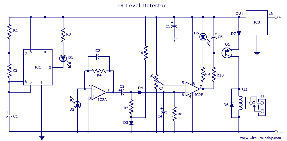
The circuit illustrates the use of a 555 Timer IC in an infrared (IR) detector configuration. It features a duty cycle of 0.8 milliseconds, a frequency of 120 Hz, and a peak current of 300 mA. The 555 Timer IC...

This stereo amplifier utilizes the NE5517/A and features an excellent tracking accuracy of 0.3 dB, which is typical. The offset can be adjusted using the potentiometer, Rp. For AC-coupled amplifiers, the potentiometer can be substituted with two 5.1 k...
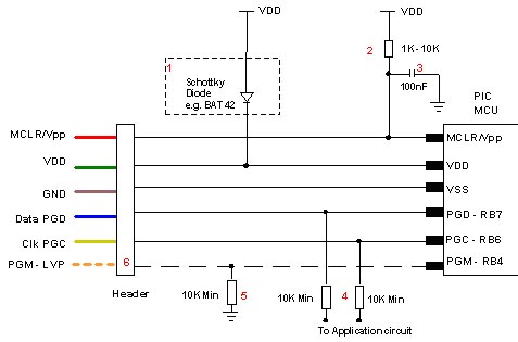
Microchip does not recommend any specific circuit for In-Circuit Serial Programming (ICSP). Various diagrams exist for different tools, such as Pro Mate and PICKit2, which feature similar circuitry with minor variations. Some schematics may suggest resistor values that are...