
555 Timer IC For IR Detector Circuit

The 555 Timer IC is a versatile device commonly utilized in various timing, pulse generation, and oscillator applications. In the context of an IR detector circuit, the 555 Timer can be configured in either monostable or astable mode, depending on the specific requirements of the application.
In this particular configuration, the circuit operates in astable mode, generating a continuous square wave output. The duty cycle of 0.8 milliseconds indicates the time duration the output remains high during each cycle, while the frequency of 120 Hz determines how often the cycle repeats per second. The peak current of 300 mA indicates the maximum current the circuit can supply to drive connected components, such as IR LEDs or phototransistors.
The circuit typically includes a few essential components: resistors, capacitors, and the 555 Timer IC itself. The resistors set the timing intervals, while the capacitor determines the charge and discharge times, which ultimately influence the frequency and duty cycle of the output signal.
When designing an IR detector, careful consideration must be given to the selection of these components to ensure the desired performance characteristics. The output from the 555 Timer can be used to drive an IR LED, which emits infrared light. This light can be reflected by nearby objects and detected by a phototransistor or photodiode, allowing the circuit to respond to the presence or absence of objects in its vicinity.
Overall, the 555 Timer IC provides a reliable and efficient solution for creating an IR detector circuit, with the specified parameters allowing for effective detection capabilities in various applications.The following circuit shows about 555 Timer IC For IR Detector Circuit. Features: duty cycle of 0.8mSec, frequency of 120Hz and 300 mA peak .. 🔗 External reference
Related Circuits
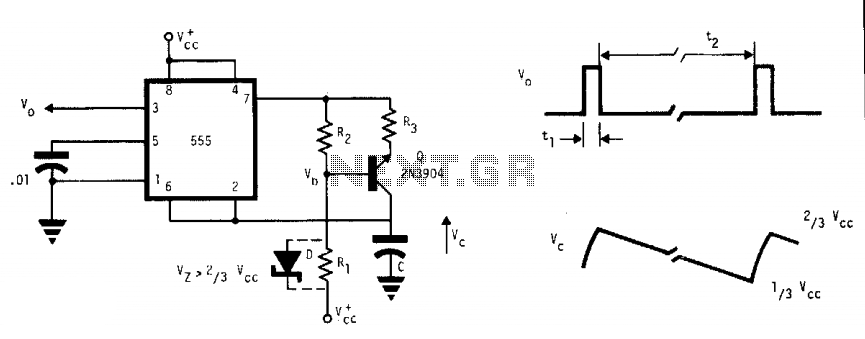
This free-running multivibrator utilizes an external current sink to discharge the timing capacitor, C. As a result, the interval can easily be 1000 times the pulse duration, t1, which defines a positive output. The voltage across the capacitor, V,...
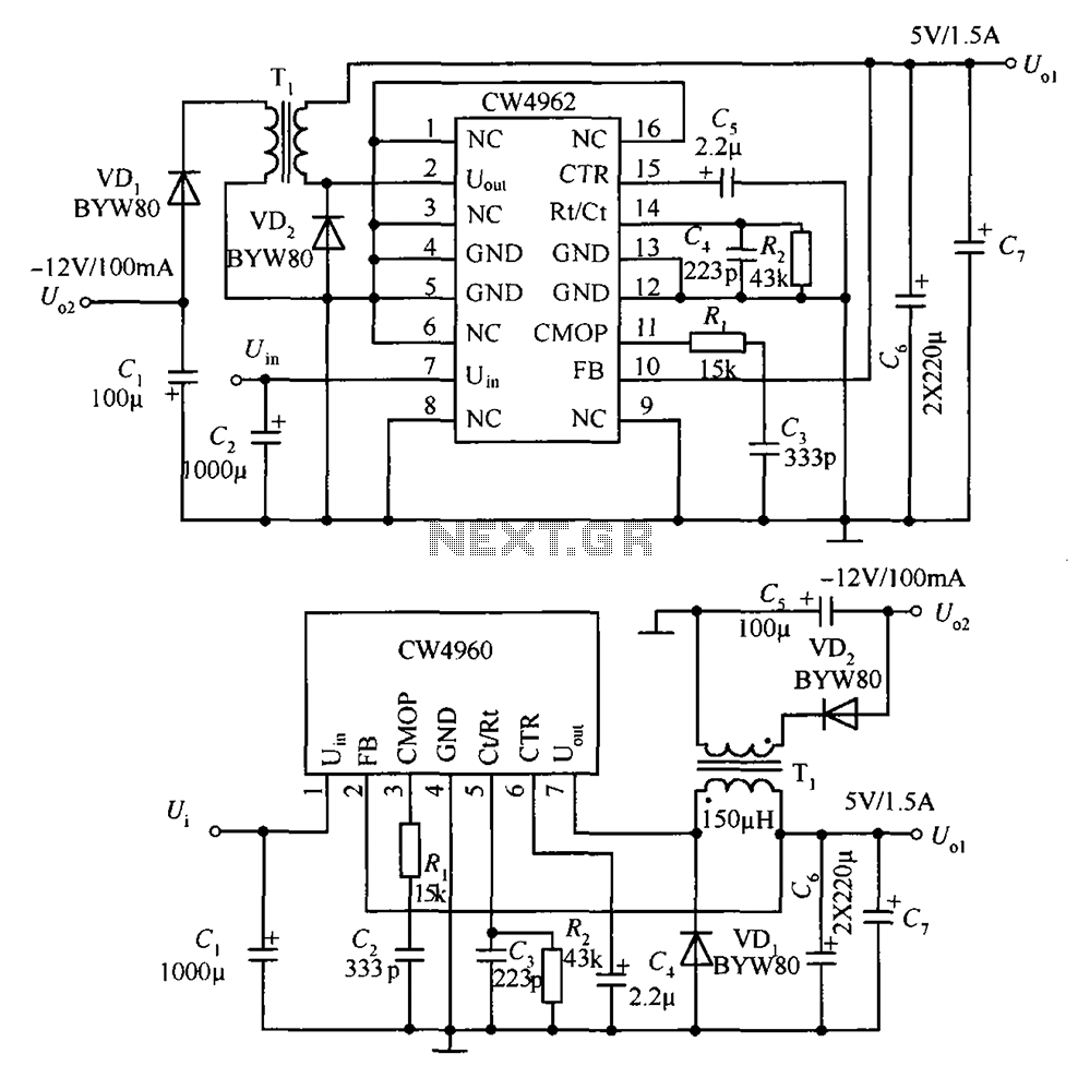
The circuit described is a stabilized power supply utilizing the CW4962 and CW4960 components, providing +5V at 1.5A and -12V at 100mA. The +5V output serves as the main power supply. The output circuit employs a transformer rather than...
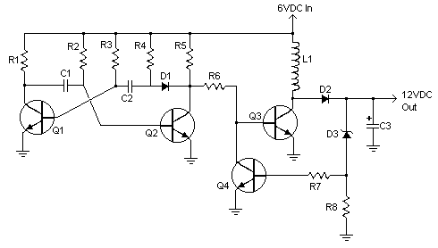
A 6V to 12V DC converter circuit is designed to convert a lower voltage of approximately 6 volts to a higher voltage of 12 volts, albeit with a reduced current rating. This inverter circuit can deliver up to 800mA...

The following circuit illustrates the Bedside Lamp Timer Circuit utilizing the CD4060 integrated circuit (IC). It operates for 30 minutes, with a blinking LED indicating the last 6 minutes of operation. The Bedside Lamp Timer Circuit is designed to provide...
The I2C serial bus is a widely used two-wire bus for small-area networks. The I2C Clock and Data lines feature open collector (or drain) outputs for each device on the network, requiring only a single pull-up resistor. This architecture...
The human ear can detect sounds ranging from 20Hz to 20KHz, with the normal range typically between 100Hz and 13KHz, depending on an individual's age and health. For accurate measurements, a range of 20Hz to 20KHz is used. Sounds...