
Thyristor AC torque motor speed control circuit 2

The circuit operates by utilizing the three thyristors (V1, V2, and V3) to control the power delivered to a motor. Thyristors are semiconductor devices that function as switches, allowing current to flow when triggered by a gate signal. In this configuration, they are arranged to manage the motor's speed effectively.
The single-junction transistor relaxation oscillator serves as the triggering mechanism for the thyristors. This oscillator generates a periodic signal, which is crucial for initiating the conduction of the thyristors. The frequency and duty cycle of this signal can be adjusted based on the desired motor speed.
Incorporating negative feedback in the speed control circuit allows for improved stability and accuracy in maintaining the motor's speed. This feedback mechanism continuously monitors the motor's performance and adjusts the triggering signal accordingly, ensuring that any variations in speed are corrected in real-time.
The master adjust potentiometer (RPi) plays a critical role in fine-tuning the system. By varying the resistance, the potentiometer alters the voltage level at the input of the trigger circuit, which in turn modifies the firing angle of the thyristors. This adjustment allows for precise control over the torque output of the motor, enabling it to respond effectively to varying load conditions.
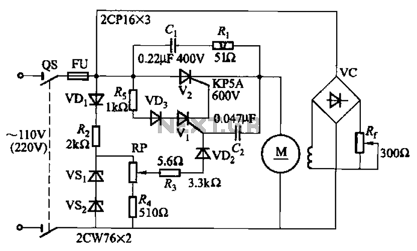
Overall, this circuit design is well-suited for applications requiring adjustable motor speed and torque control, leveraging the advantages of thyristors and feedback mechanisms for enhanced performance. Circuit shown in Figure 3-181. Main circuit consists of three thyristor Vi-V3 components. Trigger circuit single-junction transistor relaxation oscillator. Speed circuit has ne gative feedback. Master adjust potentiometer RPi, can change the torque of the motor speed.
Related Circuits
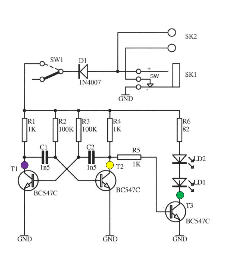
The schematic circuit presented below illustrates an infrared transmitter. The infrared beam is emitted in a nearly line-of-sight manner towards another device equipped with an infrared receiver. The displayed waveforms represent the output voltages from two intermediate stages (purple...
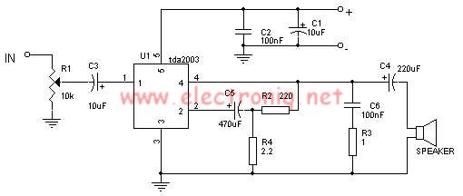
The TDA2003 audio amplifier integrated circuit can be used to design a straightforward 10-watt power audio amplifier for a 2-ohm load or 4 watts for a 4-ohm load. The TDA2003 offers high output current capacity (up to 3.5A) and...
A 100W resistance-triggered motor control circuit designed for arc welding machines. It features an adjustment potentiometer (Rr) that can modify the DC motor excitation current. Additionally, a regulator (RP) is included to adjust the DC motor armature voltage, enabling...
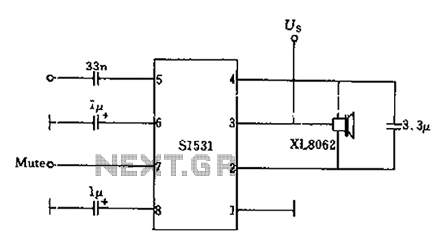
The battery voltage is 1V for a low-frequency amplifying circuit, which can operate with a power supply voltage ranging from 1V to 1.7V, making it suitable for use with small batteries. The circuit provides an output power of 80mW...
The circuit utilizes a dual sound multi-frequency encoding signal to modulate the emitted carrier frequency, forming a DTMF encoding wireless calling system. It incorporates the DTMF encoding circuit UM97085 and the decoding circuit YN9101 to create a micro wireless...
This battery backup circuit can be integrated into surveillance systems or alarm controls to provide power during mains power failures. The battery backup will immediately take over the load without any delay, and the circuit is simple to construct....