
QX1 QX2 series magnetic starter Y- reduced-voltage starting circuit

The circuit depicted in Figure 3-36 is a critical component of a three-phase motor control system. It demonstrates the configuration of the starter contact closure, which is essential for initiating the motor operation. The motor's stator windings are represented as U1, V1, W1 for the first set and U2, V2, W2 for the second set, indicating the dual winding arrangement typical in three-phase motors.
The starter contact closure, as referenced in Table 3-1, provides a systematic approach to energizing the motor. This closure is responsible for completing the circuit and allowing current to flow through the stator windings, which generates a rotating magnetic field necessary for motor operation. The interaction between the stator windings and the rotor creates torque, enabling the motor to perform work.
In practical applications, the design and layout of the circuit must ensure that the starter contacts are rated appropriately for the motor's operational current and voltage. It is also essential to incorporate protective elements such as fuses or circuit breakers to prevent damage to the motor and associated circuitry in the event of overloads or short circuits.
Furthermore, attention should be given to the phase sequence of the stator windings, as incorrect phasing can lead to reverse rotation of the motor. Proper labeling and connection of terminals U1, V1, W1, U2, V2, and W2 are crucial to maintain the correct operational parameters and ensure reliable performance of the motor system.
Overall, the configuration shown in Figure 3-36 is foundational for understanding the operation of three-phase motors and their control mechanisms, highlighting the importance of precise electrical connections and protective measures in motor applications. Circuit shown in Figure 3-36. Starter contact closure is shown in table 3-1. Figure, Ul, Vi, wl and U2, vz, W2 are the first three-phase stator windings of the motor terminal.
Related Circuits
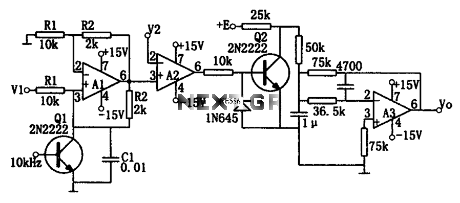
As illustrated in the dividing circuit diagram, A1 consists of a voltage-controlled current source, A2 functions as a voltage comparator, and A3 is configured as an active low-pass filter. When the time constant R1C1 is equal to the clock...
It is sometimes necessary to monitor a device that generates a relatively short pulse to indicate a change of status. If the duration of the input signal is too short, the RFC-1/B may not have enough time to capture...
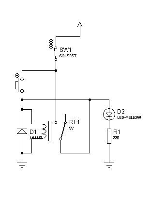
The circuit can also be triggered by logic ICs (TTL/CMOS) using the appropriate interfacing method. Another relay is typically used to serve as the trigger button when interfacing ICs with the latching relay circuit. The described circuit utilizes a latching...
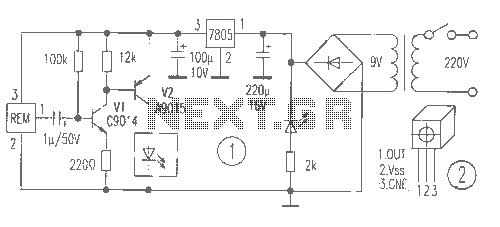
The receiver provides two TV signals, one for the living room and another for the bedroom, along with a satellite receiver. Watching television in the bedroom is convenient in Taiwan; however, when watching television in the living room, it...
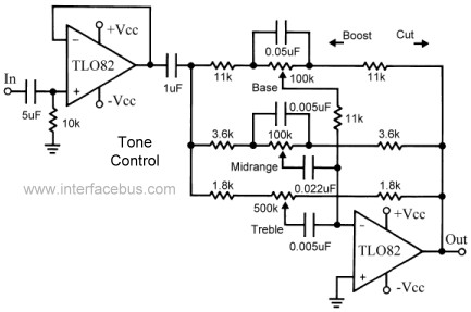
This topic continues the coverage of audio tone controls. The first entry started with a passive tone control circuit using different RC filter configurations and introduced an active filter. The second entry showed a fully designed 2-band active tone...
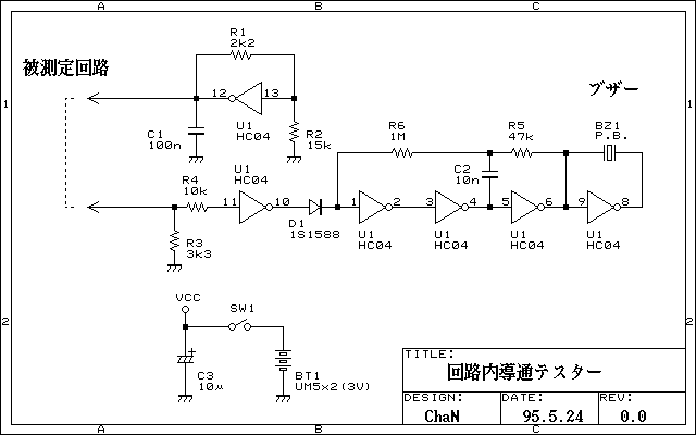
Continuity tester to check continuity in the circuit (Insakittochekka) is. The continuity check over the circuit board wiring that can be checked at a lower voltage semiconductors do not conduct contained in the circuit, you can just check the...