
5 division circuit schematic

The described circuit functions as a voltage divider with specific characteristics and configurations. The voltage-controlled current source (A1) is crucial for adjusting the output current based on the input voltage, allowing for dynamic control of the circuit's behavior. The voltage comparator (A2) plays a critical role in comparing the input voltage levels and providing a digital output signal that indicates whether the input voltage exceeds a certain threshold. This function is essential for applications requiring precise voltage monitoring and control.
The active low-pass filter (A3) is designed to smooth out the output signal from the voltage comparator, thereby reducing high-frequency noise and ensuring a stable output voltage. This filter is particularly important in applications where signal integrity is paramount. The time constant defined by R1 and C1 directly affects the filter's response time, making it vital to select components with stable temperature characteristics to maintain consistent performance across varying environmental conditions.
The relationships between the voltages in the circuit are critical for its operation. The equation Vo = V2E/V1 indicates that the output voltage (Vo) is directly influenced by the ratio of V2 to V1, scaled by the factor E. This relationship allows for predictable behavior of the circuit under different input conditions, making it suitable for a variety of electronic applications.
Overall, the circuit's design, utilizing components such as the HA2-2520 for the voltage-controlled current source and the LM101A for both the voltage comparator and the low-pass filter, ensures reliable operation within specified voltage limits. This configuration is well-suited for applications requiring precise voltage division and filtering in electronic systems. As shown in FIG dividing circuit, A1 composed of a voltage-controlled current source, A2 is a voltage comparator, A3 composition active low pass filter. When the time constant R1C1 equal to the clock pulse period T, the relationship between the output and the input of the circuit is: Vo -V2E/V1, so that if E 1V, there Vo -V2/V1, V1, V2 are positive requirements and limited to less than 10V, V2 is slightly lower than V1. Resistors R1, R2 and capacitor C1 requires a temperature stable element. A1 is HA2-2520, A2, A3 for the LM101A.
Related Circuits
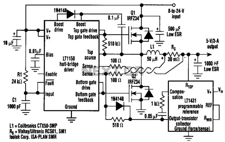
This regulator achieves 90% efficiency with a 12-V input and a 5-V output. It utilizes the LT1158 and LT1431 components from Linear Technology, Inc. High efficiency is accomplished by synchronously switching two power MOSFETs in a step-down switching regulator....
The circuit operates in a parallel-fed configuration, as the DC plate current does not pass through the inductor. R3 can be substituted with an RF choke if desired. Capacitor C3 prevents B+ from appearing across the variable capacitor, which...
This simple circuit tests speakers, microphones, transformers, and voltage. It is essentially a very low-frequency oscillator that generates extremely short, distinctive pulses. The sound produced is easy to hear and allows for precise localization, making it ideal for checking...
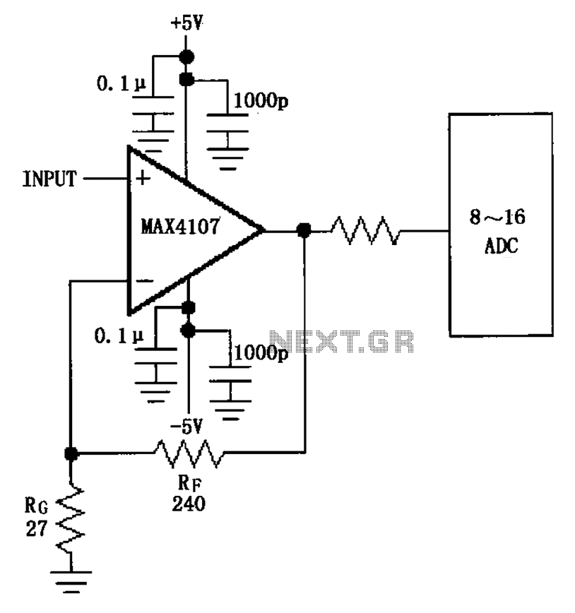
The inverting gain circuit utilizing the MAX4107 is configured as an ADC input buffer. The gain of the amplifier is established by the ratio of resistors RF and RG, which set the gain figure to approximately 10. The inverting gain...
An arrangement was established that functions effectively. In the siren circuit, the reed switch was shorted as illustrated. The power supply was removed, and a new configuration was created. The described siren circuit utilizes a reed switch, which is a...
This sensitive FM radio tuner is an ideal circuit for hobbyists who wish to construct their own tuners rather than purchasing a pre-assembled product. The FM radio tuner circuit is designed to receive frequency modulation signals, providing a clear and...