
Audio Sound Effects Circuit

The sound effects circuit operates by manipulating the input audio signal from the electric guitar, introducing non-linearities that result in distortion. The primary components of this circuit typically include operational amplifiers (op-amps), diodes, resistors, and capacitors.
The circuit begins with the input stage, where the guitar signal is fed into a buffer amplifier. This buffer prevents loading effects that could alter the sound characteristics. Following this, the signal is directed to a distortion stage, which often employs an op-amp configured in a non-inverting mode. The gain of this stage can be adjusted using a variable resistor, allowing users to control the level of distortion.
Diodes are commonly used in the feedback loop of the op-amp to clip the signal peaks, creating the desired distortion effect. The choice of diodes can significantly affect the tonal characteristics, with silicon diodes producing a sharper clipping compared to germanium diodes, which yield a warmer sound.
After the distortion stage, the signal may pass through a tone control circuit consisting of capacitors and resistors that shape the frequency response, allowing users to enhance or attenuate specific frequencies. Finally, the output stage may include another buffer to drive the output signal to an amplifier or effects chain without degradation.
This circuit can be housed in a compact enclosure with input and output jacks, a power supply connector, and control knobs for gain and tone adjustments, providing musicians with a versatile tool for enhancing their sound. The design can be adapted with additional features such as a bypass switch, LED indicators, or even a built-in reverb effect, making it a valuable addition to any guitarist's setup.This sound effects circuit is designed to work as a signal distorter. If used with an electric guitar, it allows the production of special sound effects. T.. 🔗 External reference
Related Circuits
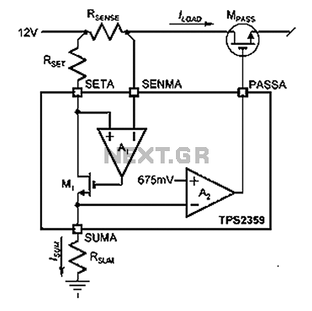
Amplifier A1 utilizes the voltage across the sense resistor sensors to monitor the load current ILOAD. The power management channel employs a similar circuit, with the distinction of integrating resistors RSENSE and RSET. Amplifier A1 is configured to measure the...
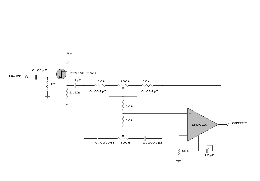
This circuit is a simple series tone control circuit. It utilizes the surgical amplifier LM301A. The JFET 2N3684 provides high input impedance and low noise for the unbuffered operational amplifier, which operates in an equalizer (EQ) configuration. Further details...
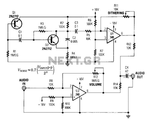
By introducing a small amount of noise to a signal intended for digitization (approximately 0.7 bits), where n represents the number of bits, for instance, an 8-bit signal with a peak-to-peak voltage of 2 V would result in a...
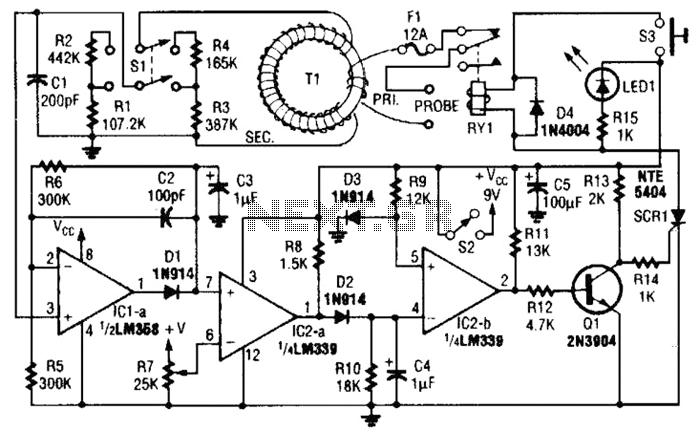
This circuit is an adjustable electronic circuit breaker that features a toroidal transformer designed to sense a 60-Hz load current. The transformer, labeled as T1, has a two-turn winding for the primary side and 100 turns of #30 gauge...
A Butterworth filter is a type of filter characterized by a frequency response that is flat within the passband region. This filter was first described by British engineer Stephen Butterworth. A Butterworth filter is designed to provide a maximally flat...
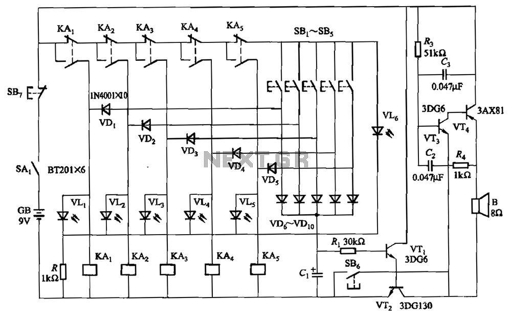
A relay-style circuit designed for a five electronic responder group. This circuit features self-locking capabilities, sound and light displays, time monitoring, and additional functions. The circuit includes a monitoring time button operated by the moderator. When this button is...