
Third batch start and stop cycle control circuits

The circuit employs two relays, which play a critical role in automating the motor control process. The first relay is responsible for initiating the motor operation, while the second relay manages the motor's intermittent running cycle. This dual-relay system enhances the circuit's functionality, allowing for various operational modes.
When the switch SA is placed in the right position, the circuit transitions to a continuous run mode. In this configuration, the motor receives a constant supply of power, enabling it to operate without interruption. The design of the circuit ensures that the relays can handle the necessary current and voltage levels while providing reliable operation over extended periods.
The use of relays adds a layer of safety and control, as they can isolate the motor circuit from the power supply when not in use, reducing the risk of electrical hazards. The automatic cycle run feature allows for efficient operation in applications where intermittent motor activity is required, such as in conveyor systems or automated machinery.
Overall, the circuit design is versatile, catering to both intermittent and continuous operation modes, making it suitable for various industrial applications. The careful selection of components and their arrangement ensures optimal performance and reliability in automatic control scenarios. Circuit shown in Figure 3-78. The time line also use two relays to achieve automatic control, but the line structure than simple. The line can be achieved intermittently motor automatic cycle run, it can run continuously (switch SA placed the figure to the right position).
Related Circuits
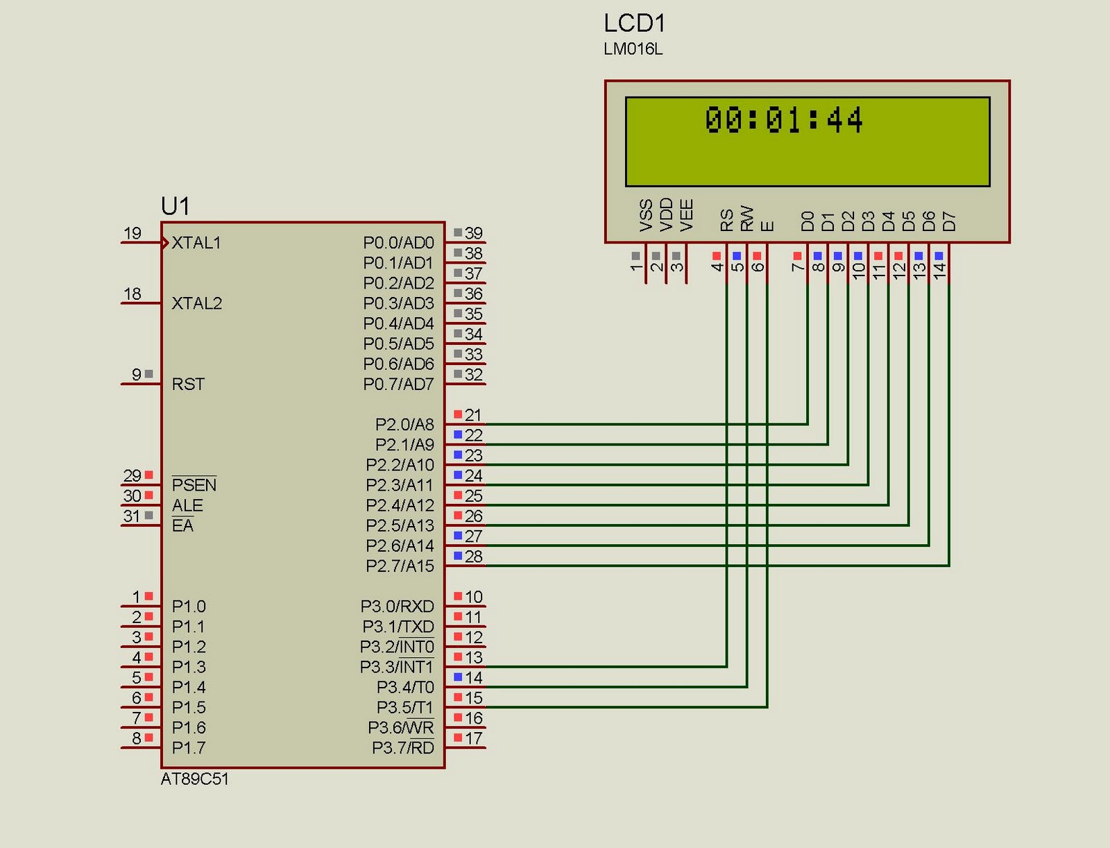
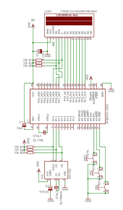
This project implements a real-time clock using the 89C51 microcontroller. The clock's data format is hours:minutes:seconds, which is displayed on a 16x2 LCD. The code has been tested and compiled using the Keil uVision compiler. The circuit diagram for...
The UBA2024 is a half-bridge integrated circuit (IC) and a 550 V lamp controller. This device features 9-ohm switches that support standard compact fluorescent lamp (CFL) applications up to 15 W. The UBA2024 is specifically designed for driving compact fluorescent...
The HC-06 module is a slave mode serial Bluetooth data link manufactured by CSR. In this project, a mobile phone communicates with the AT89C2051 microcontroller via the HC-06 module. The complexity of the communication has been encapsulated within a...
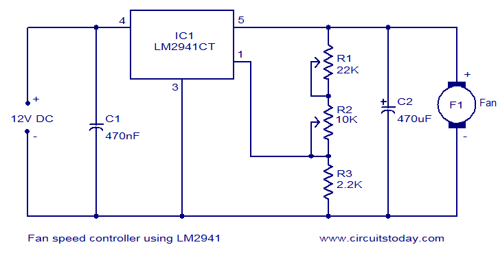
Numerous electronic circuits designed for fan speed control have been documented, and this one presents an alternative method. The circuit diagram illustrates a 12V DC fan speed controller utilizing the LM2941CT integrated circuit, which is a low dropout 1A...
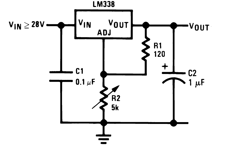
The LM338 integrated circuit (IC) from Texas Instruments is a versatile component that can be configured in various ways to create high-quality power supply circuits. The first circuit demonstrates the typical wiring format around the IC, providing an adjustable...
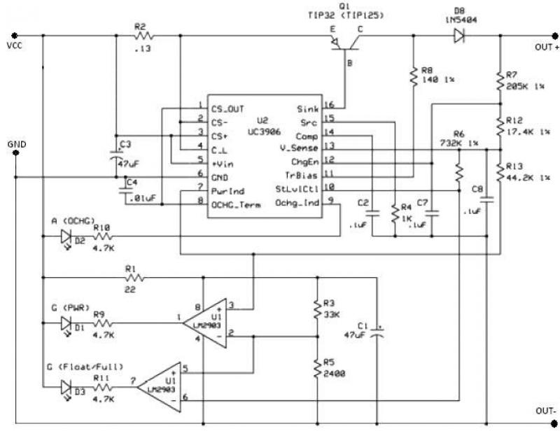
The UC3906 battery charger circuit controller includes all necessary circuitry to manage the charge and hold cycles for sealed lead-acid batteries. This circuit is specifically designed to deliver the appropriate charging voltage and current based on the battery's temperature...