
Fan speed controller using LM2941

The 12V DC fan speed controller circuit employs the LM2941CT voltage regulator, which is notable for its low dropout voltage, enabling it to maintain a stable output voltage even with minimal input voltage overhead. This characteristic is particularly advantageous in battery-operated applications where efficiency is critical. The IC's built-in protections, including reverse polarity, thermal shutdown, and short-circuit protection, enhance the reliability and safety of the circuit, making it suitable for various applications where fan operation needs to be controlled under varying load conditions.
The circuit's configuration allows for easy adjustment of the fan speed through the use of potentiometers. The adjustment current (Iadj) is crucial for regulating the output voltage, which directly influences the fan's operational speed. By modifying the resistance of potentiometer R2, the user can fine-tune the output voltage. This design aspect provides flexibility, allowing the user to achieve the desired airflow based on specific cooling requirements.
In practical implementation, the circuit should be laid out on a suitable PCB to minimize parasitic inductance and resistance, ensuring stable operation. Proper heat dissipation measures must be considered, especially since the LM2941CT can supply up to 1A of current. Adequate thermal management will prevent overheating and extend the lifespan of the circuit components. Additionally, the choice of the fan should align with the circuit's specifications to ensure compatibility and optimal performance.Many electronic circuits related to fan speed controlling have been published here and this one is just another approach. The circuit diagram shown here is of 12V DC fan speed controller using the IC LM2941CT which is a low drop out 1A voltage regulator.
The IC has a dropout voltage as low as 0. 5 and has also many useful features like power supply reverse protection, thermal protection, short circuit protection etc. The maximum output current the IC can source is 1A. The 12V DC supply is connected between the Vin (pin4) and ground (pin3) of the IC. The load, which is the fan, is connected across the Vout (pin5) and ground (pin3) of the IC. The network comprising of potentiometers R1, R2 and resistor determines adjust current (Iadj) of the IC. By varying the Iadj using the POT R2 we can adjust the output voltage of the IC and hence the fan speed.
🔗 External reference
Related Circuits
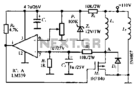
The LM339 comparator IC (Integrated Circuit) is utilized to enhance the functionality of electric circuits. A potentiometer (B) is incorporated to adjust the desired setpoint, while a feedback signal is generated by resistor (R). A significant pressure point is...
A pulse width modulator generates a PWM signal, which consists of pulses with a constant frequency while the duty cycle varies according to a modulating signal. A pulse width modulator (PWM) is an essential component in various electronic applications, particularly...
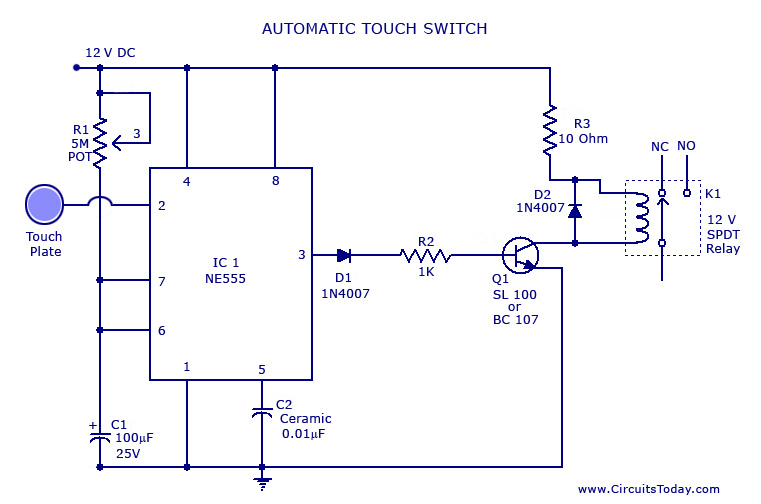
A touch switch circuit schematic utilizing a 555 integrated circuit (IC). When the touch plate is activated, a relay is switched ON for a predetermined duration, which can also be adjusted. The touch switch circuit employs a 555 timer IC...
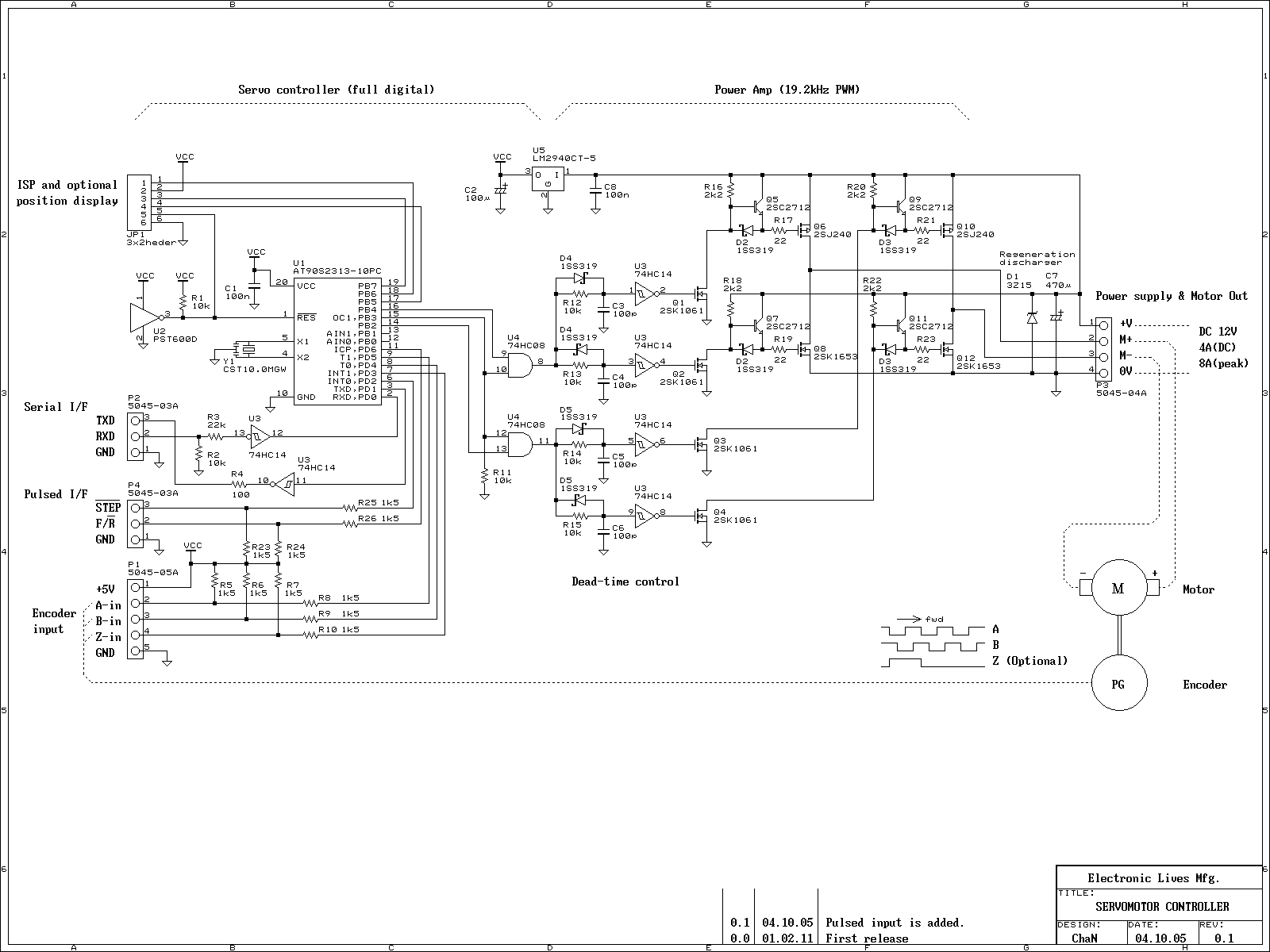
This is an experiment on the closed loop DC servomotor control system (SMC). It will be able to be used for practical use with/without some modifications. The closed loop servo mechanism requires real-time servo operations, such as position control,...
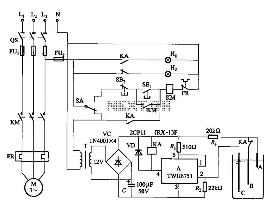
The power switch integrated circuit A features a straightforward design with high sensitivity, ensuring reliable operation. It is part of an automatic liquid level control circuit. When the water level at electrode B drops below 2 feet (0V), circuit...
The FSK demodulator is an electronic device that converts the FSK signal into a serial digital signal. FSK modulation is utilized to transmit digital serial data. The FSK (Frequency Shift Keying) demodulator serves a critical function in digital communication systems...