
Intermittent start and stop cycle control circuit of the four

The circuit comprises two delay stages that serve to control the operation of a motor. The first delay circuit utilizes an RPi adjustment potentiometer, which allows for fine-tuning of the delay period. This component is crucial for setting the initial timing parameters that dictate how long the motor remains active before stopping. The second delay circuit, represented by RP2, further enhances the control over the motor's running time, providing additional flexibility in timing adjustments.
In practical applications, the use of potentiometers in delay circuits allows for user-friendly adjustments. By rotating the potentiometer knob, the resistance changes, thereby altering the time constant of the circuit. This results in a variable delay that can be tailored to meet the specific requirements of the motor operation. The timing can be adjusted within a defined range, making it suitable for various applications where precise motor control is necessary.
The integration of these delay circuits ensures that the motor can be activated or deactivated based on the desired timing, enhancing efficiency and functionality in automated systems. Additionally, the circuit design may include other components such as capacitors and transistors, which work in conjunction with the delay circuits to stabilize the operation and enhance the performance of the motor control system. Overall, the schematic provides a robust solution for controlling motor operations with adjustable timing capabilities. Circuit shown in Figure 3-79. It consists of two delay circuits, respectively. RPi adjustment potentiometer and RP2, respectively, can be changed and stop the motor running the length of time (arbitrarily changed within th).
Related Circuits
The recommendation regarding the existing phono connector is to maintain its current configuration without making significant alterations. The procedure involves replacing the electrolytic and paper capacitors, adding a three-wire line cord, and utilizing the radio in its original state....
An electrical circuit that ensures when two or more generators are connected in parallel to a power system, they share the load equally. In this arrangement, if the voltage of one generator is slightly higher than that of the...
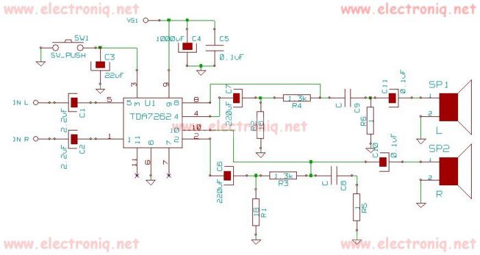
TDA7262 stereo 20 watts audio amplifier circuit design electronic project The TDA7262 is an integrated circuit designed for stereo audio amplification, capable of delivering up to 20 watts per channel. This amplifier circuit is suitable for various applications, including home...
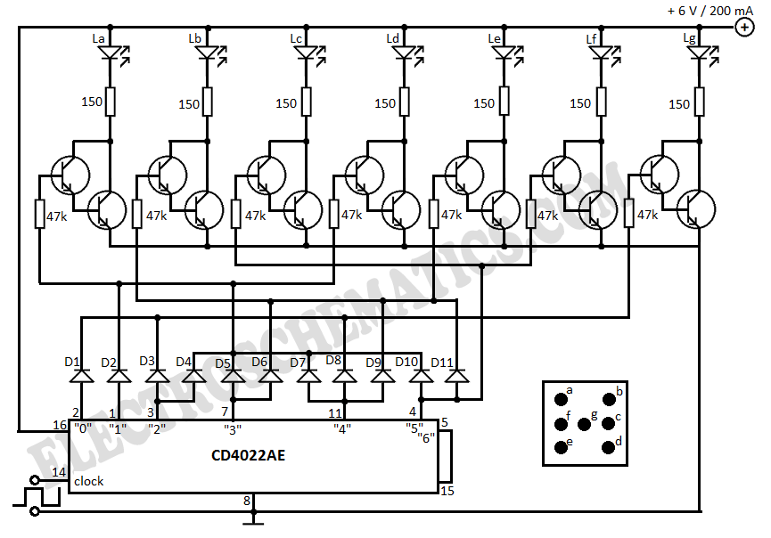
This electronic dice displays results using LEDs arranged to represent each face of a die. The circuit diagram incorporates IC 4022, which functions as a counter. The electronic dice circuit utilizes a combination of integrated circuits and discrete components to...
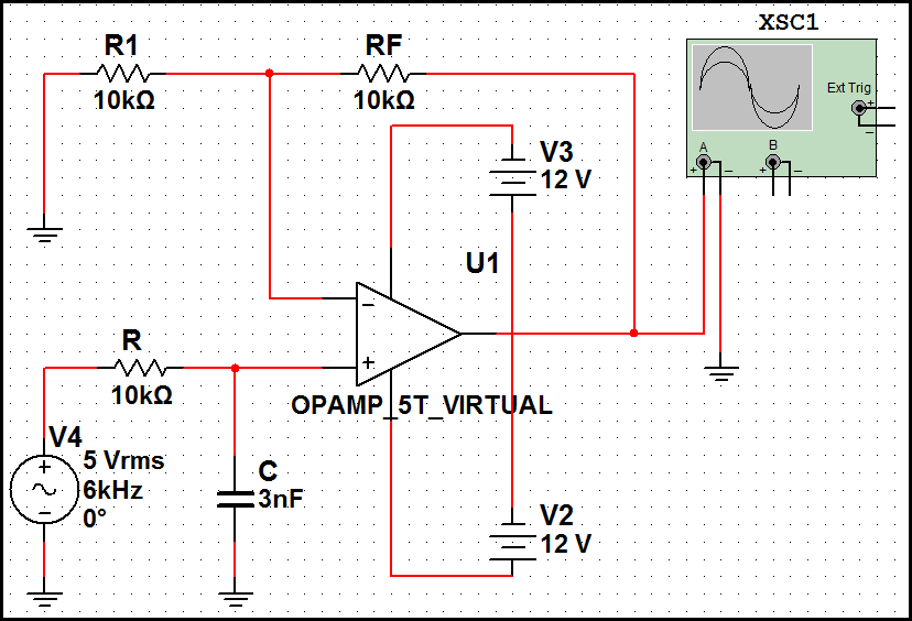
High-order filters are typically designed with two or more cascaded sections. An order 4 filter requires only one operational amplifier integrated circuit (OA IC), allowing for lower distortion. High-order filters are essential in various applications, including audio processing, signal conditioning,...
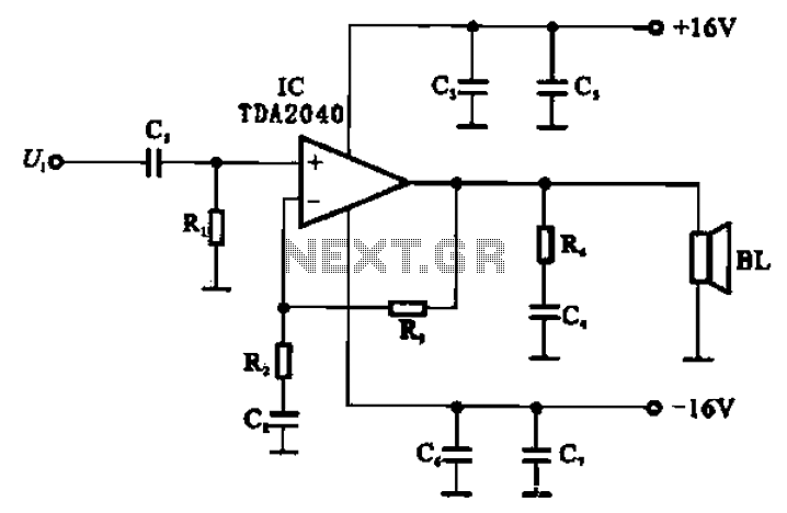
An integrated power amplifier, TDA2040 (IC), can be configured as an OCL (Output Capacitor-Less) power amplifier. The circuit, illustrated in Figure 10-10, operates using a symmetrical ±1V dual supply voltage. The OCL amplifier benefits from the positive and negative...