
Electronic Dice Circuit

The electronic dice circuit utilizes a combination of integrated circuits and discrete components to simulate the rolling of a die. The primary component, IC 4022, is a binary counter that counts up to a predetermined value, in this case, six, corresponding to the faces of a standard die.
When the circuit is powered on, a push-button switch initiates the counting process. Each time the button is pressed, the counter increments its value. The output of the IC 4022 is connected to a series of LEDs, each representing one of the six faces of the die. The LEDs are configured such that only one LED is illuminated at a time, indicating the current value of the counter.
To ensure that the display is visually appealing and easy to read, the LEDs are typically arranged in a pattern that mimics the layout of a traditional die. For instance, the LED representing the number one is placed in the center, while the others are positioned to reflect their respective values.
In addition to the IC 4022, the circuit may include resistors to limit the current through the LEDs, ensuring they operate within safe limits and prolonging their lifespan. A capacitor may also be included to stabilize the power supply and prevent fluctuations that could affect the counting accuracy.
This electronic dice circuit serves as an excellent project for both educational and recreational purposes, demonstrating fundamental principles of digital electronics and circuit design. It can be further enhanced by adding features such as sound effects or a more complex random number generation algorithm to improve the randomness of the results.With this electronic dice the result is displayed with LEDs that are placed so every dice face is shown. In the circuit diagram, IC 4022 is used to count t.. 🔗 External reference
Related Circuits
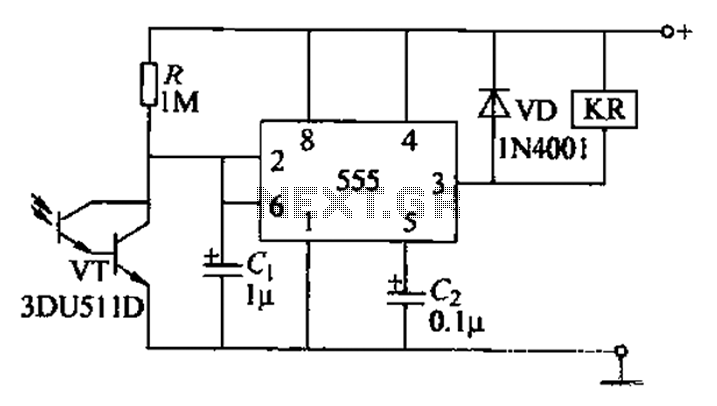
The circuit utilizes a Darlington-type phototransistor as the sensing element, which enhances sensitivity to low light levels, making it suitable for detecting reflected light signals. When the Darlington phototransistor is exposed to light, its resistance decreases, causing the voltage...
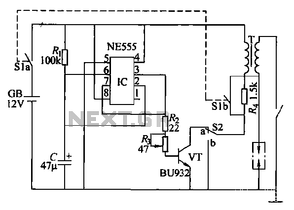
This paragraph describes an easy car alarm circuit that utilizes fewer components and is simple to produce. The circuit consists of an automobile anti-theft alarm system based on the NE555 timer, a power switch (VT), and a switch (S2),...
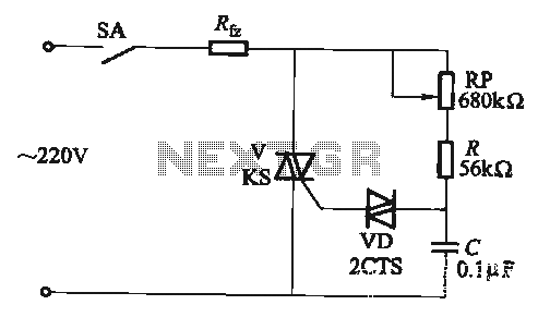
The adjustment potentiometer RP allows for the modification of the TRIAC conduction angle, facilitating temperature control applications. The adjustment potentiometer (RP) serves a crucial role in controlling the conduction angle of the TRIAC, which in turn regulates the power delivered...
The circuit was designed to obtain signals through amplitude modulation, exhibiting good sensitivity and selectivity. Amplitude modulation. The amplitude modulation (AM) circuit is engineered to effectively capture and process radio frequency signals. The design focuses on achieving high sensitivity, allowing...
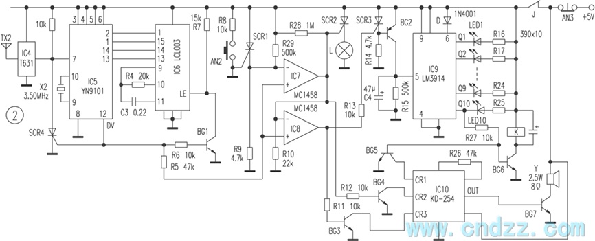
The wireless calling device consists of a calling unit and a host. These two components communicate using a DTMF encoder pulse. Each calling unit is assigned a unique code, although the circuits are identical. The calling unit is depicted...
The following circuit illustrates a 5 Zone Anti-Theft Circuit Diagram. This circuit is based on the CMOS 4050B IC. Features: the system may comprise in... The 5 Zone Anti-Theft Circuit utilizes the CMOS 4050B integrated circuit, which is a hex...