
TL081 4 Order Filter Circuit

High-order filters are essential in various applications, including audio processing, signal conditioning, and communication systems. The design of an order 4 filter using a single operational amplifier (OA) IC can significantly reduce complexity and cost while maintaining performance.
In this configuration, the filter can be implemented using a Sallen-Key topology or a multiple feedback (MFB) structure. The Sallen-Key design is favored for its simplicity and ease of implementation. It consists of a resistor-capacitor (RC) network that determines the cutoff frequency and the quality factor (Q) of the filter.
To construct the order 4 filter, two cascaded second-order sections can be utilized. Each section comprises two resistors and two capacitors, with the OA IC serving as the active component. The transfer function of the filter can be expressed in terms of the component values, allowing for precise tuning of the filter characteristics.
The selection of component values is critical in achieving the desired filter response. Resistors and capacitors should be chosen to meet the specifications for cutoff frequency, gain, and phase response. Additionally, the operational amplifier must have sufficient bandwidth and low noise characteristics to ensure the integrity of the signal is preserved.
To achieve lower distortion, careful attention should be paid to the layout and grounding of the circuit. Proper decoupling of the power supply to the OA IC is also essential to minimize noise and ensure stable operation.
Overall, the design of a fourth-order filter using a single OA IC offers a practical solution for applications requiring high performance with reduced complexity.Filters with high orders are designed usually with 2 or more cascaded sections. This order 4 filter need only one OA IC , so we can achieve lower distorsio.. 🔗 External reference
Related Circuits
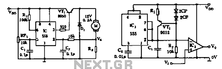
The circuit consists of a 555 motor automatic governor configuration. It includes flip-flops, a 555 timer, and a switching tube. A sampling circuit is formed by connecting R7 and the motor in series. RP1 is used to control the...
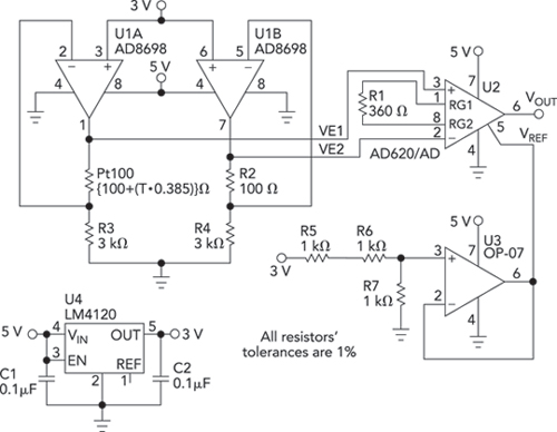
Bridge circuits are widely used for conditioning signals from resistive sensors. These circuits are sensitive to minor changes in resistance, providing a differential output from a single current or voltage source. However, the sensors connected to a passive bridge...
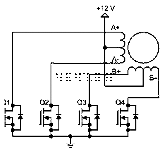
A bipolar stepper motor drive circuit is presented, utilizing eight transistors to operate two phases. This bipolar drive circuit can accommodate both four-wire and six-wire stepper motors; however, it is primarily designed for four-wire bipolar configurations, which can significantly...
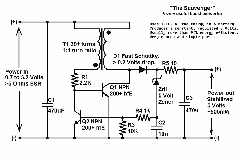
Presented here is a significant advancement in the design of simple, cost-effective, and efficient boost converters. To achieve an effective design, it is essential to convert current to voltage as efficiently as possible. This circuit excels in this regard. The...

Digital Command Control (DCC) provides significant advantages over traditional DC analog control systems, primarily due to its simplified wiring. DCC enables the individual control of multiple locomotives on the layout without requiring electrical isolation of track sections. The main...
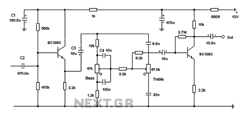
Based on the classic Baxendall tone control circuit, this design offers a maximum cut and boost of approximately 10 dB at 10 kHz and 50 Hz. Since the controls are passive, the final transistor provides a slight boost. The...