
Intermittent start and stop cycle control circuit Five of a

The circuit operates using a transistor multivibrator configuration, which is designed to generate oscillations. This type of circuit typically consists of two transistors that alternately switch on and off, creating a square wave output. The coupling between the two branches is achieved through capacitive and resistive elements, forming an RC timing circuit that influences the frequency of oscillation.
The inclusion of the RPi adjustment potentiometer provides a means to fine-tune the timing characteristics of the circuit. By adjusting this potentiometer, the user can modify the charge and discharge times of the timing capacitors, thereby controlling the duration of the output pulse. This feature is particularly useful for applications where precise motor control is required, allowing for adjustments to be made while the motor is in operation.
The RP2 component also plays a critical role in the timing adjustments, serving as an additional variable resistor that can be configured to alter the resistance in the timing circuit. This flexibility ensures that the multivibrator can be tailored to meet specific operational requirements, enhancing the overall functionality of the system.
In summary, the circuit in Figure 3-80 exemplifies a versatile multivibrator design that integrates timing control through adjustable components, making it suitable for various applications where motor speed and operation timing are crucial. Circuit shown in Figure 3-80. Which controls part of the transistor multivibrator. Multivibrator is a strong positive and negative feed-forward amplifier, its two branches are coupled RC timing circuit, so there is no steady state. RPi adjustment potentiometer and RP2. You can change each time the motor is running and stop time.
Related Circuits
Have you ever accidentally left your front door ajar and had a pet escape? Here is a smart solution to this problem. The circuit is relatively simple but serves as a great example of using a compact circuit to...
This 300W RF power amplifier for an FM transmitter utilizes 2 x TP9383 transistors. It operates within the 88 - 108 MHz frequency band. The 300W RF power amplifier is designed specifically for FM transmission applications, providing high power output...
This shows the overall circuit diagram of the power control unit. On the left, there is a main relay controlled by the key switch. The power control unit circuit diagram illustrates the primary components and their interconnections for managing electrical...
Typically, when a car door is closed, the dome light turns off immediately. This circuit allows the dome light to gradually fade in brightness before eventually turning off. An electronic transformer dims halogen lamps and is a straightforward device...
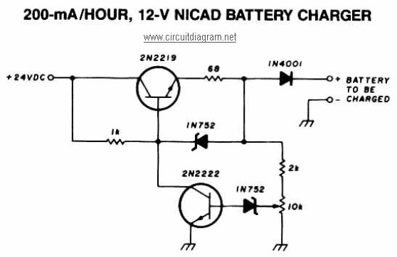
A 12V NiCAD battery charger circuit with a charging rate of 200mA per hour. This circuit initially charges the battery at 75mA until it reaches a full charge, after which the current is reduced to a trickle rate. The...
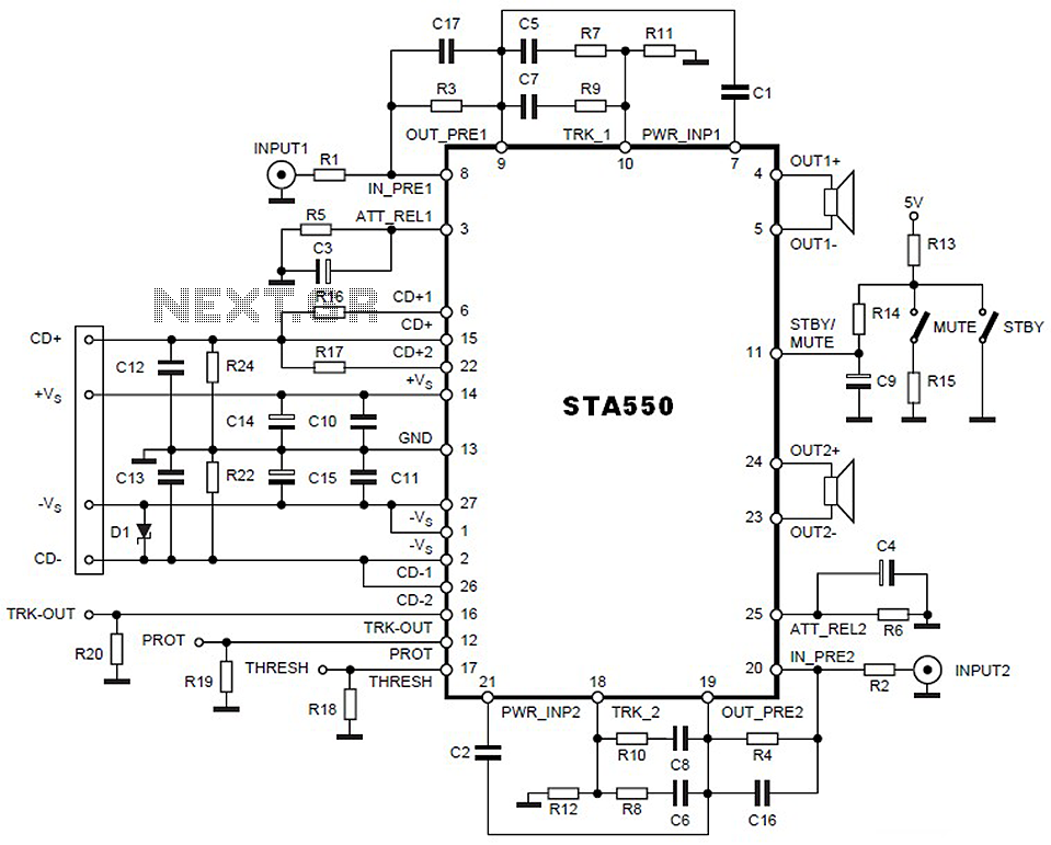
This is a 2 x 70W audio power amplifier circuit built using a single IC STA550. The amplifier circuit requires a few external components, primarily resistors and capacitors, and is straightforward to design. The STA550 audio amplifier can provide...