
Door Ajar Alarm Circuit

The door ajar alarm circuit utilizes a CD4011 NAND gate IC, which is well-suited for low-power applications. The circuit operates as follows: when the door is closed, the bar magnet's proximity to the reed switch keeps the switch in a closed state, resulting in a low logic level at the input pins of the CD4011. This condition prevents the output from switching high, thus disabling the beeper.
Once the door is opened, the bar magnet moves away from the reed switch, causing the switch to open and the input pins of the CD4011 to receive a high logic level. This transition triggers the output of the NAND gate to go low, activating the beeper circuit. The beeper, typically a piezoelectric speaker, produces an audible alarm that alerts users of the door's ajar status. The intermittent beeping, occurring at a frequency of approximately 450 Hz, provides a clear indication without being overly disruptive.
In terms of component selection, the CD4011 can operate within a voltage range that is compatible with a standard 9V battery. Additional components may include resistors and capacitors for signal conditioning and timing, ensuring the beeping occurs at the desired rate. The entire assembly should be secured within a durable plastic enclosure to protect the electronic components from environmental factors while maintaining accessibility for battery replacement.
This circuit exemplifies a practical application of basic electronic principles to create a functional and effective door ajar alarm system, enhancing pet safety and providing peace of mind to pet owners.Ever accidentally left your front door ajar and had a pet escape Here is a smart solution to this problem. The circuit is fairly simple but a great example of using a tiny circuit to get the job done. All you need is a CD4011 IC plus a handful of components. In this door ajar alarm/beeper circuit, a bar magnet-reed switch combination is used as t he door sensor. When the door is closed, as per mechanical arrangement, the bar magnet near the reed switch close its switch contacts. Now the beeper circuit built around CD4011 (IC1) is disabled by the logic low state at its input terminals (pins 1&12).
When door is opened the beeper is enabled by the logic high state and the speaker starts beeping intermittently at a rate of about 0. 5 secs on/0. 5 secs off. Frequeny of this gated aural output is near 450 Hz. After assembling, enclose the circuit including the reed switch, in a plastic enclosure and mount it on the door frame.
Next fit the bar magnet in the door exactly in alignment with the reed switch so that when door is closed the bar magnet is at the close vicinity of the reed switch. For powering the circuit, use an alkaline type 9V compact battery. 🔗 External reference
Related Circuits

The amplifier circuit utilizes negative current feedback, which ensures that the load current is primarily influenced by the input signal rather than the loudspeaker's impedance. The inductor current from the loudspeaker generates a voltage across resistor R7, which is...
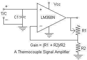
Continuing with the thermocouple interface concept, the next step is to amplify the TC's millivolt signal into a more readable analog voltage, on the order of 0 to 5VDC. This simple circuit fits the bill. The LM358N is a...

This is an infrared emission circuit diagram. The NE555 circuit generates a 40 kHz pulse, which is sent by the infrared emission control SE303 after being amplified by VT. The remote receiver and infrared dimming circuit are composed of...

The filament of an incandescent bulb serves as the sensing component of the circuit. When there is no airflow, the resistance of the filament is low. In contrast, when airflow is present, the resistance decreases because the moving air...

This is a simple metal detector utilizing a TDA2822 and several NPN transistors. An arrow indicates the signal flow direction from the Emitter of transistor T3 to the 10nF capacitor C4, which is opposite to the typical left-to-right flow...
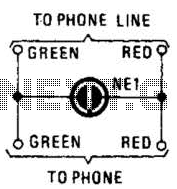
A neon lamp can easily be added to the phone line to act as a ring indicator. It is perfect for times when you cannot hear the phone. The integration of a neon lamp as a ring indicator in a...