
Intermittent start-stop cycle control circuit of seven b

The circuit utilizes the 555 timer IC in an astable configuration to create a pulse-width modulation (PWM) signal that drives the motor. The frequency and duty cycle of the PWM signal are determined by the resistors RPi and RPz, along with a timing capacitor connected to the 555 IC. By adjusting these potentiometers, the user can fine-tune the duration that the motor remains in operation versus the duration it remains off, allowing for flexible control over the motor's performance.
In this configuration, the 555 timer operates by charging and discharging the timing capacitor, which generates a square wave output. This output can be connected to a transistor or a relay, which acts as a switch to control the power supplied to the motor. When the output from the 555 IC is high, the transistor is turned on, allowing current to flow through the motor and initiating its operation. Conversely, when the output is low, the transistor turns off, cutting power to the motor and halting its operation.
The choice of components, such as the specific values of RPi and RPz, will affect the motor's operational characteristics, including its speed and the responsiveness of the start/stop cycles. Proper selection of the timing capacitor is also crucial, as it influences the frequency of the PWM signal. This circuit design is particularly useful in applications requiring automated control of motor functions, such as in robotic systems, automated doors, or conveyor belts. Circuit shown in Figure 3-82. It uses 555 IC A motor to achieve automatic control of start and stop cycles. Adjust potentiometer RPi and RPz, respectively, to change the motor running and stop times.
Related Circuits
The completed Solar CD Two LED circuit is presented with components labeled to correspond with the schematic. Although the soldered circuit may appear different from the schematic, the connections remain consistent, which is crucial. To transition from the schematic...
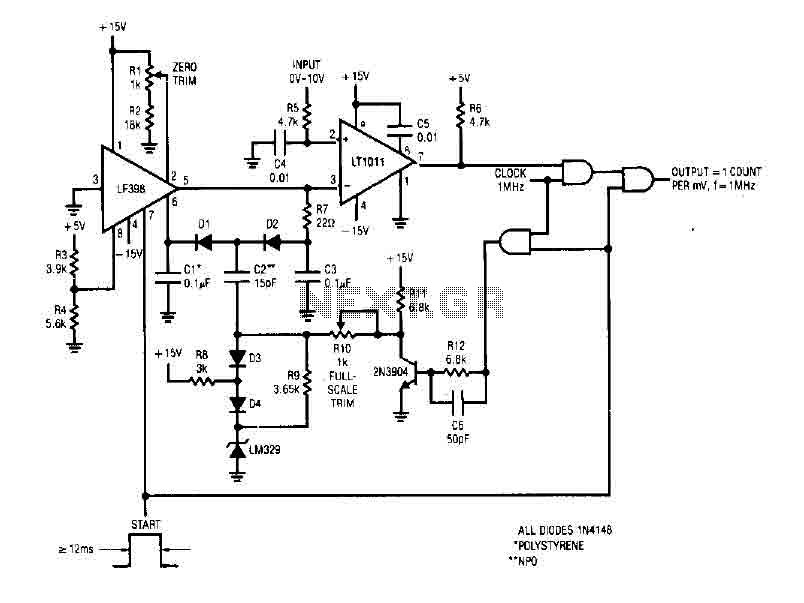
The simple 4-digit converter circuit has an output count of 1, designed for a frequency range from f-IMHz to 10.000 MHz. All diodes used in the circuit are IN4146 "POLYSTYRENE" NPO. The circuit utilizes the LF398 at the input...
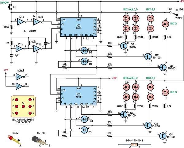
This circuit utilizes two 4516 integrated circuits (ICs) to simulate a game involving two dice. A switch is included to select whether one or two dice will be activated with each press. A 9-volt battery is sufficient for power...
This circuit produces a two-tone effect similar to the cuckoo song. It is suitable for use in doorbells or other applications due to its integrated audio amplifier and loudspeaker. When utilized as a sound effect generator, it can be...
This circuit illustrates a lighting control circuit diagram with a power rating of approximately 300-350W. Features include low cost, simplicity, and operation at 120V AC voltages. Components: .. The lighting control circuit designed for 300-350W applications is intended to provide...
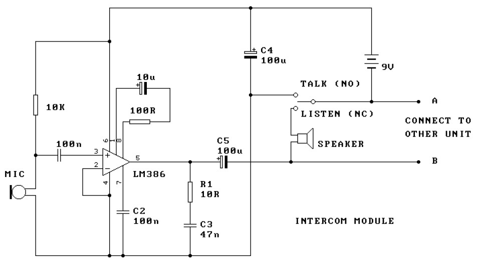
This is a two-station intercom system that operates using two wires connecting each intercom unit. Each unit is self-contained, equipped with its own battery, speaker, microphone, and amplifier circuit. An LM386 audio power amplifier is utilized, which is widely...