
300-350W Lighting Control

The lighting control circuit designed for 300-350W applications is intended to provide a reliable and efficient means of controlling lighting systems in residential or commercial environments. The circuit operates at a standard voltage of 120V AC, making it suitable for use in regions with this voltage specification.
The schematic typically includes a few key components: a power source, a control switch, a relay or triac for switching, and load elements such as lamps or LED fixtures. The power source connects to the control switch, which allows the user to turn the lighting on or off as desired. When the switch is activated, it sends a signal to the relay or triac, which acts as an electronic switch to control the flow of current to the load.
The use of a relay is common in such circuits due to its ability to handle high currents safely while providing electrical isolation between the control circuit and the high-power load. Alternatively, a triac can be used for more advanced control, such as dimming capabilities, allowing for variable brightness of the connected lighting fixtures.
The components selected for this circuit should be rated appropriately for the expected load. For example, the relay should have a current rating above the maximum load current, and the control switch should be rated for 120V AC operation. Additionally, proper fusing or circuit protection should be included to prevent damage from overload conditions.
Overall, this lighting control circuit is designed to be cost-effective and straightforward, making it accessible for DIY enthusiasts and suitable for various lighting applications. Proper attention to component ratings and circuit design will ensure reliable performance and safety in operation.This circuit shows about 300-350W Lighting Control Circuit Diagram . Features: Cheap to build, Simple circuit, 120V AC voltages. Component: .. 🔗 External reference
Related Circuits

The DPT Transmitter is a dual-powered voice transmitter designed to operate in two modes: a high-power mode for long-range transmission and a low-power mode for extended battery life. It functions at a low power level of 100 mW and...
Watching the time on a mobile phone in the dark can cause discomfort due to the strong contrast between bright and dark backlighting. To address this issue, the "ICON" model is utilized, which operates in standby mode with a...
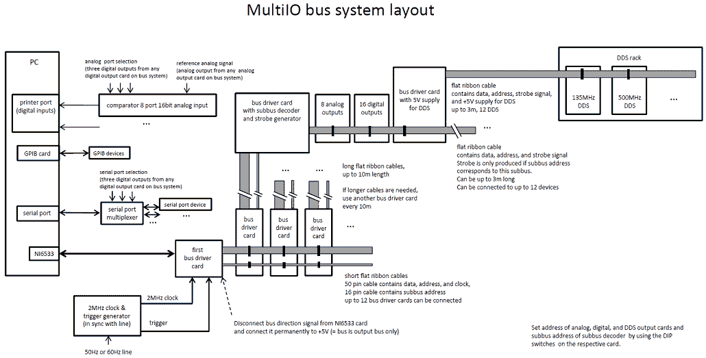
We have developed a powerful yet inexpensive and easy to construct experiment control system. The construction of the system together with the control software is described here. All circuits and software are free to download and use for nonprofit....
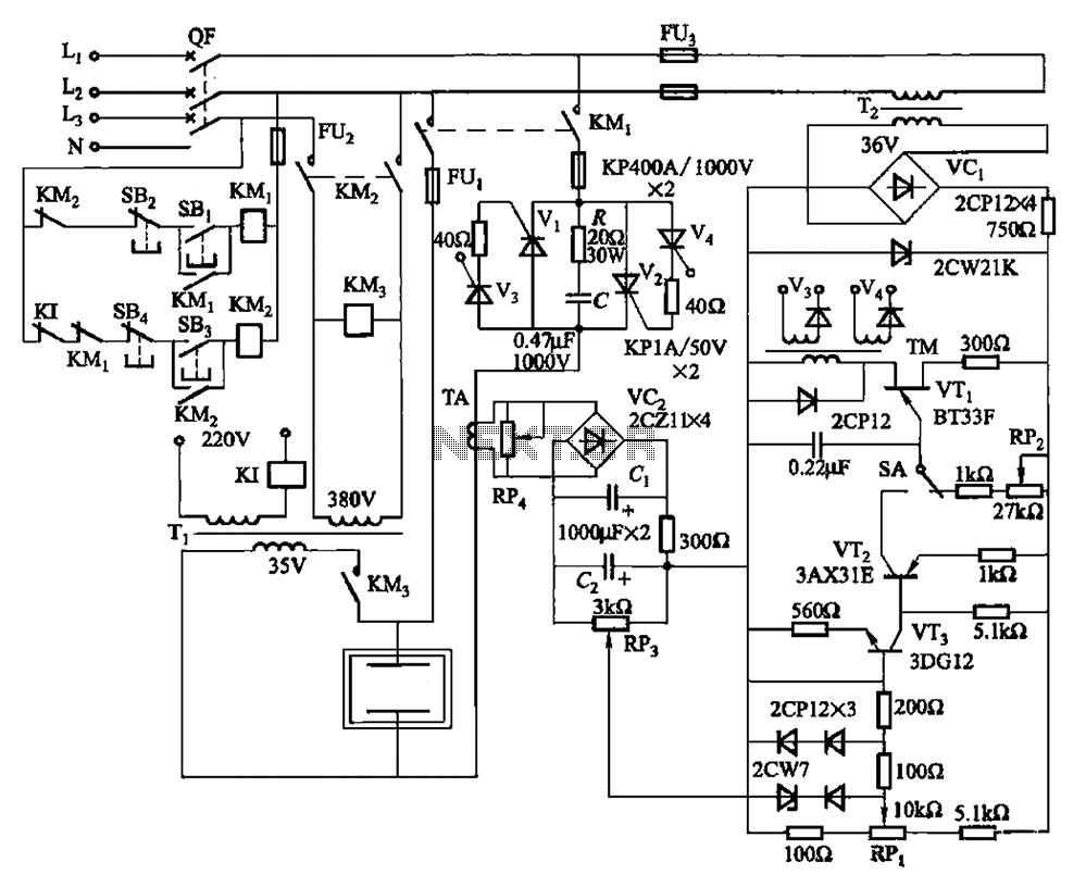
80 kW resistance salt bath furnace control circuit. The salt bath resistance furnace is a high-power device that employs fast start and temperature control technology to significantly save energy. The circuit includes a single-junction transistor (VTi) used as a...
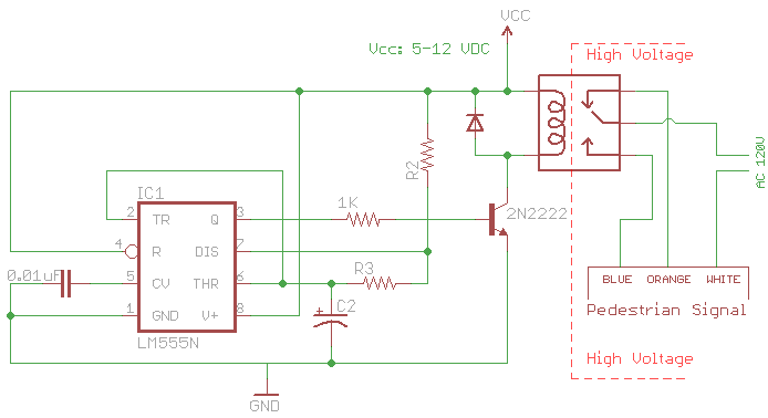
The signal consists of three wires: common, "walk," and "don't walk." This document outlines the operation of the unit's countdown feature. The information and examples provided here are applicable to other models and brands of signals. The signal was...
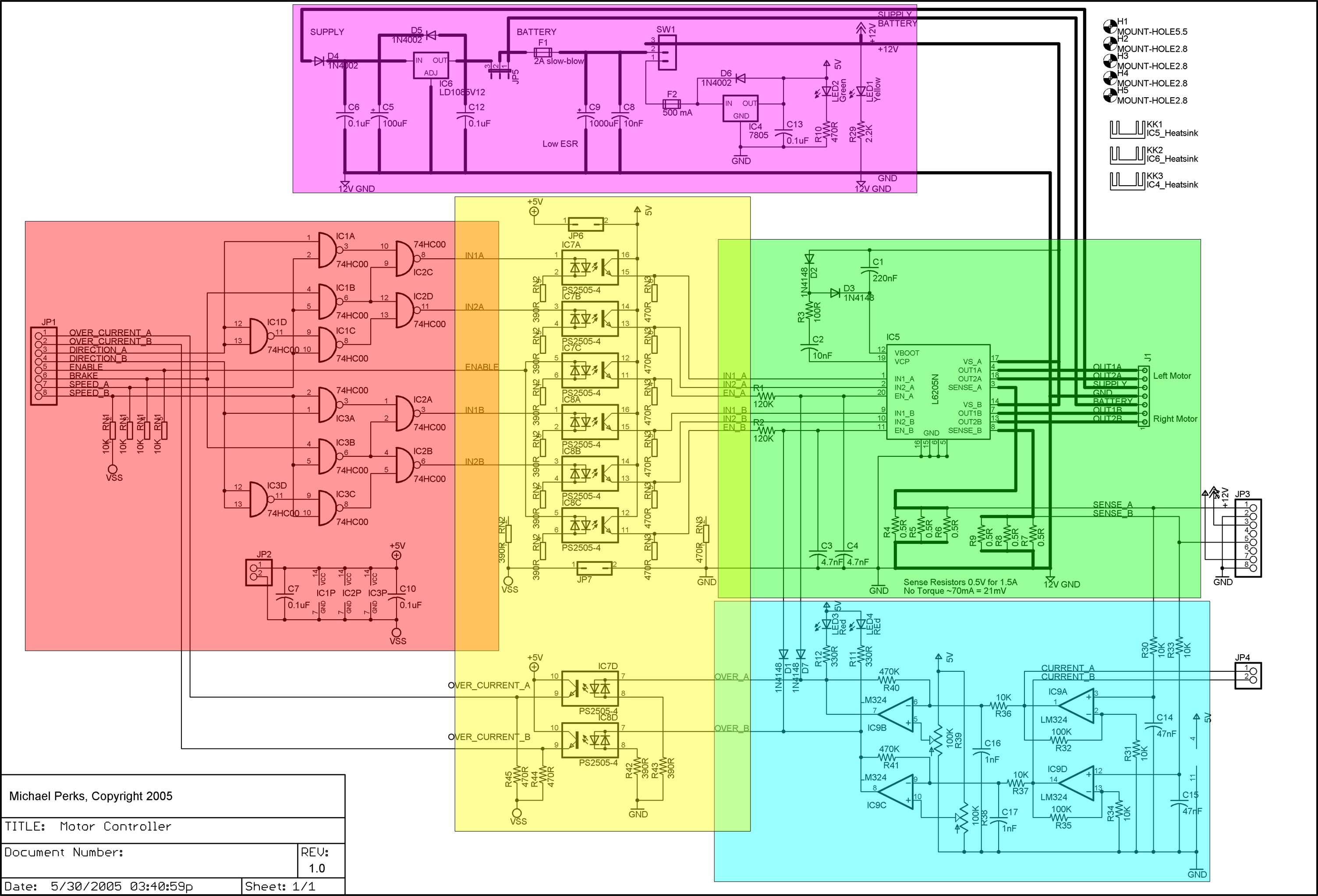
A dual DC motor controller employs an H-bridge controller chip. In addition to the standard features of the H-bridge driver chip, such as thermal and over-current protection, the circuit supports dual 12V/5V regulated power supplies, sign/magnitude and brake driver...